Ultrasonic motor
a technology of ultrasonic motors and motors, applied in piezoelectric/electrostrictive/magnetostrictive devices, piezoelectric/electrostriction/magnetostriction machines, electrical apparatus, etc., can solve the problems of difficult control of the vibration amplitude of the elastic body, difficult to achieve stable, and fine motion of the driven body, etc., to achieve stably and finely.
- Summary
- Abstract
- Description
- Claims
- Application Information
AI Technical Summary
Benefits of technology
Problems solved by technology
Method used
Image
Examples
first embodiment
[0033]An ultrasonic motor according to the present invention will be described below with reference to FIGS. 1 to 7
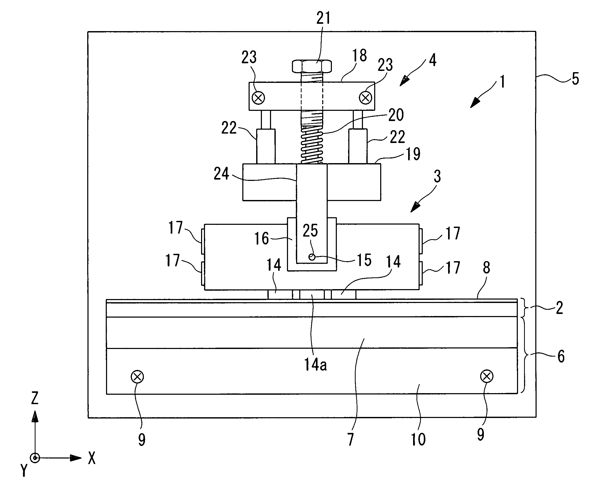
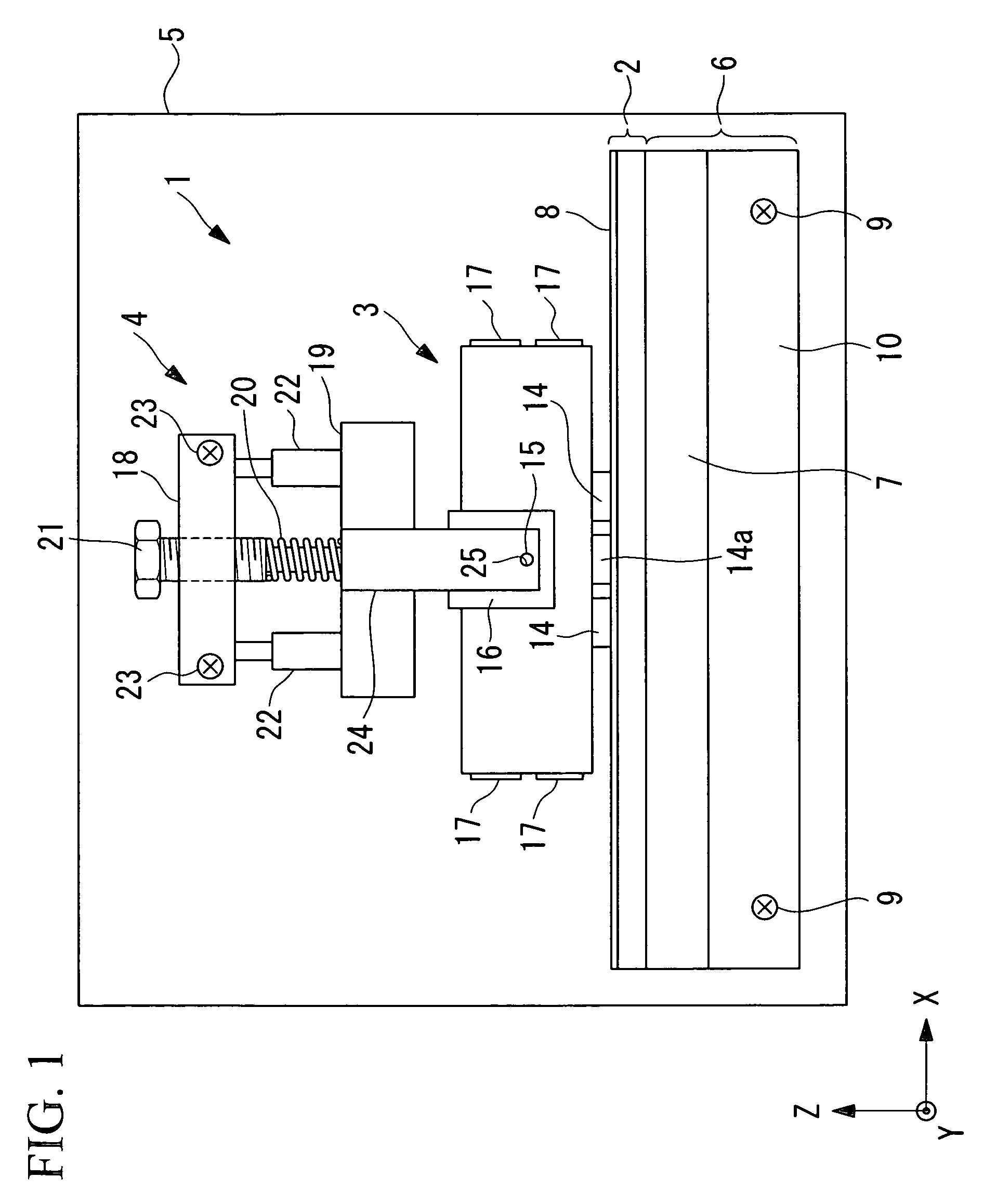
[0034]As shown in FIG. 1, an ultrasonic motor 1 according to this embodiment includes a driven body 2, an ultrasonic vibrator 3 disposed in contact with the driven body 2, and a pressing unit 4 for pressing the ultrasonic vibrator 3 against the driven body 2.
[0035]The driven body 2 is fixed to a movable member 7 of a linear bearing 6, which is secured to a base 5. A sliding plate 8 made of, for example, zirconia ceramic is bonded to the driven body 2 on the surface contacting the ultrasonic vibrator 3. Screws 9 secure a fixed member 10 of the linear bearing 6 to the base 5.
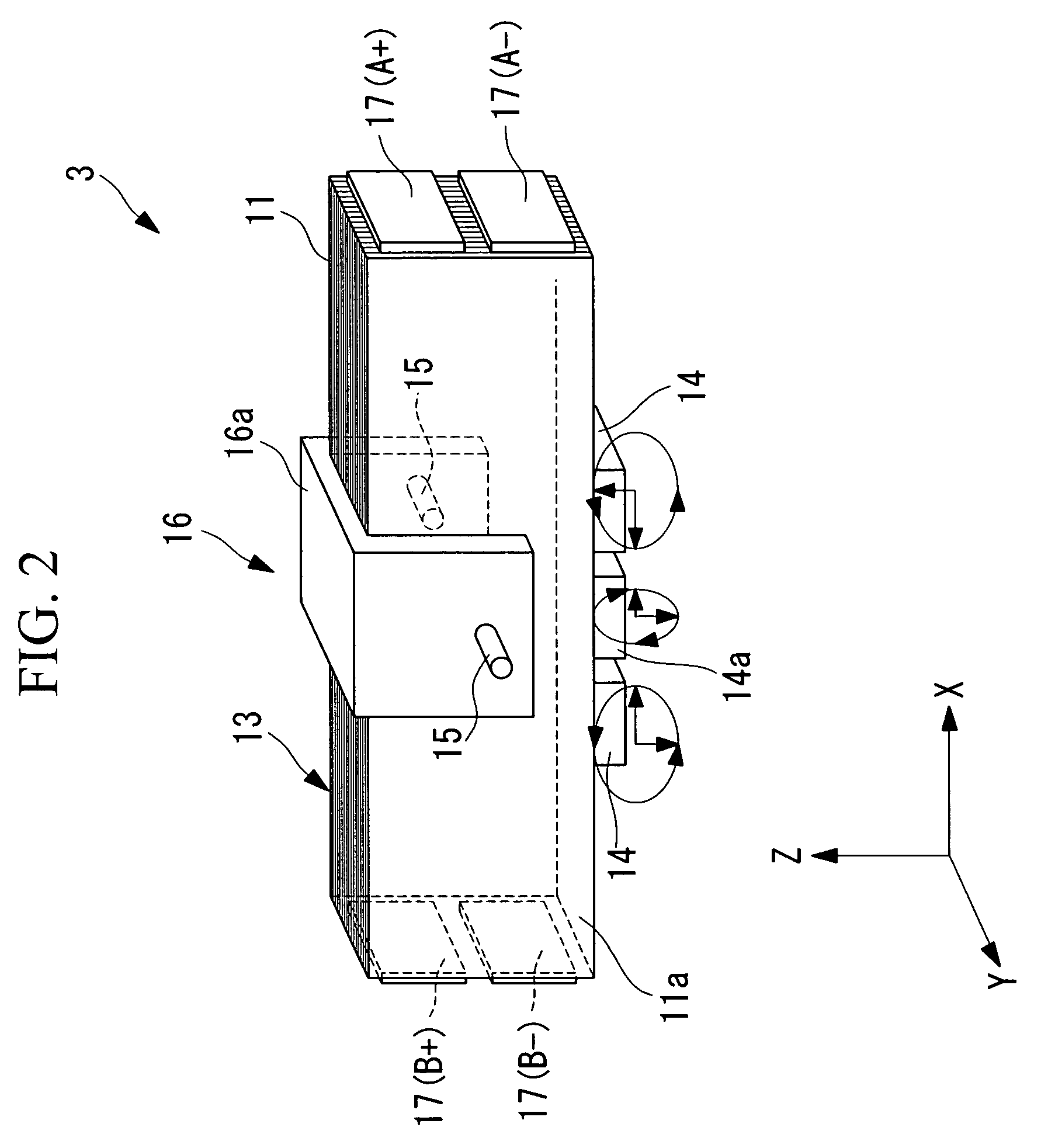
[0036]As shown in FIGS. 2, 3, 4A and 4B, the ultrasonic vibrator 3 includes a rectangular-block-shaped piezoelectric layered member 13, first friction-contact members (output terminals) 14 and a second friction-contact member (output terminal) 14a bonded to one of the side surfaces of the piezoelectri...
second embodiment
[0064]Next, an ultrasonic motor 2 according to the present invention will be described using FIG. 7.
[0065]As shown in FIG. 7, the ultrasonic motor 2 according to this embodiment differs from that in the first embodiment described above in that an ultrasonic vibrator 33 having two second friction-contact members 14b between the first friction-contact members 14 is provided. The other elements are identical to those in the first embodiment described above, and therefore, a description of those elements shall be omitted here.
[0066]Parts identical to those in the first embodiment are assigned the same reference numerals.
[0067]In this embodiment, the first friction-contact members 14 have a phase difference of 180 degrees, and the second friction-contact members 14b have substantially the same phase. The second friction-contact members 14b have phase differences of 90 degrees with respect to the first friction-contact members 14. On the other hand, the locii of the first friction-contact...
third embodiment
[0070]Next, an ultrasonic motor according to the present invention will be described using FIG. 8.
[0071]As shown in FIG. 8, the ultrasonic motor according to this embodiment differs from that in the embodiments described above in that an ultrasonic vibrator 43 having first friction-contact members 14 and third friction-contact members (output terminals) 14c is provided. The other elements are identical to those in the embodiments described above, and therefore, a description of those elements shall be omitted here.
[0072]Parts identical to those in the embodiments described above are assigned the same reference numerals.
[0073]The first friction-contact members 14 have been described in the first embodiment, and the description thereof shall not be repeated here.
[0074]The third friction-contact members 14c are bonded to the piezoelectric layered member 13 at the two ends in the longitudinal direction (the X direction in FIG. 8). When a first-order longitudinal vibration is generated i...
PUM
 Abstract
Description
Claims
Application Information
 - R&D
- Intellectual Property
- Life Sciences
- Materials
- Tech Scout
- Unparalleled Data Quality
- Higher Quality Content
- 60% Fewer Hallucinations
Browse by: Latest US Patents, China's latest patents, Technical Efficacy Thesaurus, Application Domain, Technology Topic, Popular Technical Reports.
© 2025 PatSnap. All rights reserved.Legal|Privacy policy|Modern Slavery Act Transparency Statement|Sitemap|About US| Contact US: help@patsnap.com


