System and method to control flowfield vortices with micro-jet arrays

a technology of flow field and micro-jet array, which is applied in the direction of airflow influencers, drag reduction, wings, etc., can solve the problems of poor performance and/or stalling of aircraft engines, potentially hazardous conditions, and downstream structures exposed to the vortices, so as to reduce downstream buffeting and fatigue of components

Active Publication Date: 2009-03-31
LOCKHEED MARTIN CORP
View PDF17 Cites 31 Cited by
  • Summary
  • Abstract
  • Description
  • Claims
  • Application Information

AI Technical Summary

Benefits of technology

[0011]The present invention provides a system or method to actively control the size and trajectory flow field vortices with micro-jet arrays that substantially addresses the above-identified needs. More particularly, the present invention provides a system or method for shedding flow field vortices from aerodynamic surfaces with active micro-jet arrays to reduce downstream buffeting and fatigue of components exposed downstream components.
[0012]Manipulating the shedding, size and trajectory of flow field vortices from an aerodynamic surface involves placing micro-jet arrays at the aerodynamic surface. The individual micro-jets are oriented generally with the flow direction of the fluid flow. These micro-jet arrays induce secondary flow structures within a boundary layer of the fluid flow. The secondary flow structures manipulate the shedding, size and trajectory of the flow field vortices from the surface. In fact, these secondary flow structures or vortices allow the inception point and trajectory and size of the flow field vortices to be actively influenced. By controlling the inception, size, and trajectory of the flow field vortices, it is possible to reduce buffeting and fatigue of downstream components.
[0013]Downstream components may include, but should not be limited to; engine inlets buried within the airframe on next generation aircraft, after body, empennage, missiles, turrets, inlet cowls and wings of an aircraft. By reducing the structural loads imposed on these components, the structure required to manage the stress loads on the components may be reduced as well. When a downstream component is an aircraft engine, potentially hazardous conditions can be avoided by preventing the aircraft engine from stalling due to flow field vortices. Additionally, when the downstream component is a submerged engine or one with a reduced or eliminated pylon, the vortices may manipulate the boundary layer obscured by the engine inlet. Such improvements allow reduced observability, improved control, reduced weight and surface area by reducing the pylon or nacelle.
[0016]Another implementation provides a method to reduce the effect of flow field vortices generated along the surfaces of an upstream vehicle on a downstream vehicle. This involves placing micro-jet arrays on aerodynamic surfaces of the upstream vehicle. These micro-jet arrays are generally oriented with the mean flow direction of the fluid flow over the upstream vehicle's aerodynamic surfaces. Micro-jet arrays introduce secondary flow structures within the boundary layer of the fluid flow over the upstream vehicle. These secondary flow structures influence the inception point, size, and trajectory of flow field vortices associated with the upstream vehicle. By properly directing flow field vortices laterally outward from the upstream vehicle, the separation in time and space between the vehicles may be reduced. This may help improve traffic problems encountered in congested airways.

Problems solved by technology

Flow field vortices generated by fluid flow over aerodynamic surfaces can buffet and fatigue any downstream structure exposed to these vortices.
Additionally, these vortices can be ingested within engine air intakes or other like air inlets leading to poor performance and / or stalling of the aircraft engines.
Stalling the aircraft engine creates a potentially hazardous condition.
Additionally, exotic aperture shapes for the inlet and outlet may cause excessive propulsion performance losses.
These vortices can not only cause damage to downstream components on an aircraft, but can seriously damage downstream aircraft as well.
Placing components, such as engines or control surfaces, in non-optimal positions in order to reduce these stresses often results in reduced vehicle performance.
Similarly, adding structural weight to support increased stress loads caused by the flow field vortices also results in reduced vehicle performance.
However, these veins result in increased weight and reduced performance over the aircrafts entire operating envelope.
However, these structure used to induce vortices are fixed and provide no mechanism to actively manipulate the vortex generation needed to improve a dynamic flow condition.

Method used


Image

  • System and method to control flowfield vortices with micro-jet arrays
  • System and method to control flowfield vortices with micro-jet arrays
  • System and method to control flowfield vortices with micro-jet arrays

Examples


Embodiment Construction

[0032]Preferred embodiments of the present invention are illustrated in the figures like numerals being used to refer to like and corresponding parts of the various drawings.

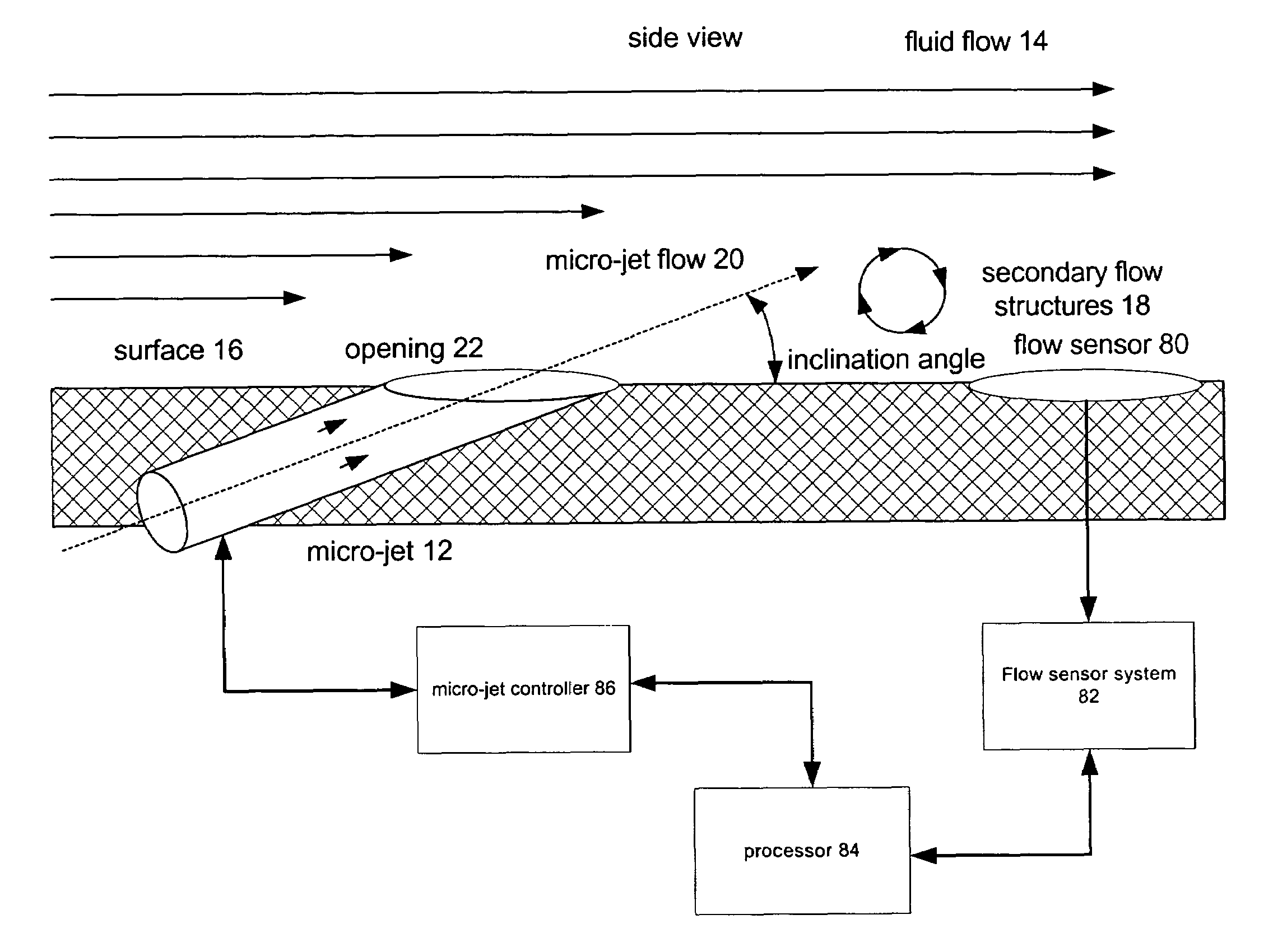
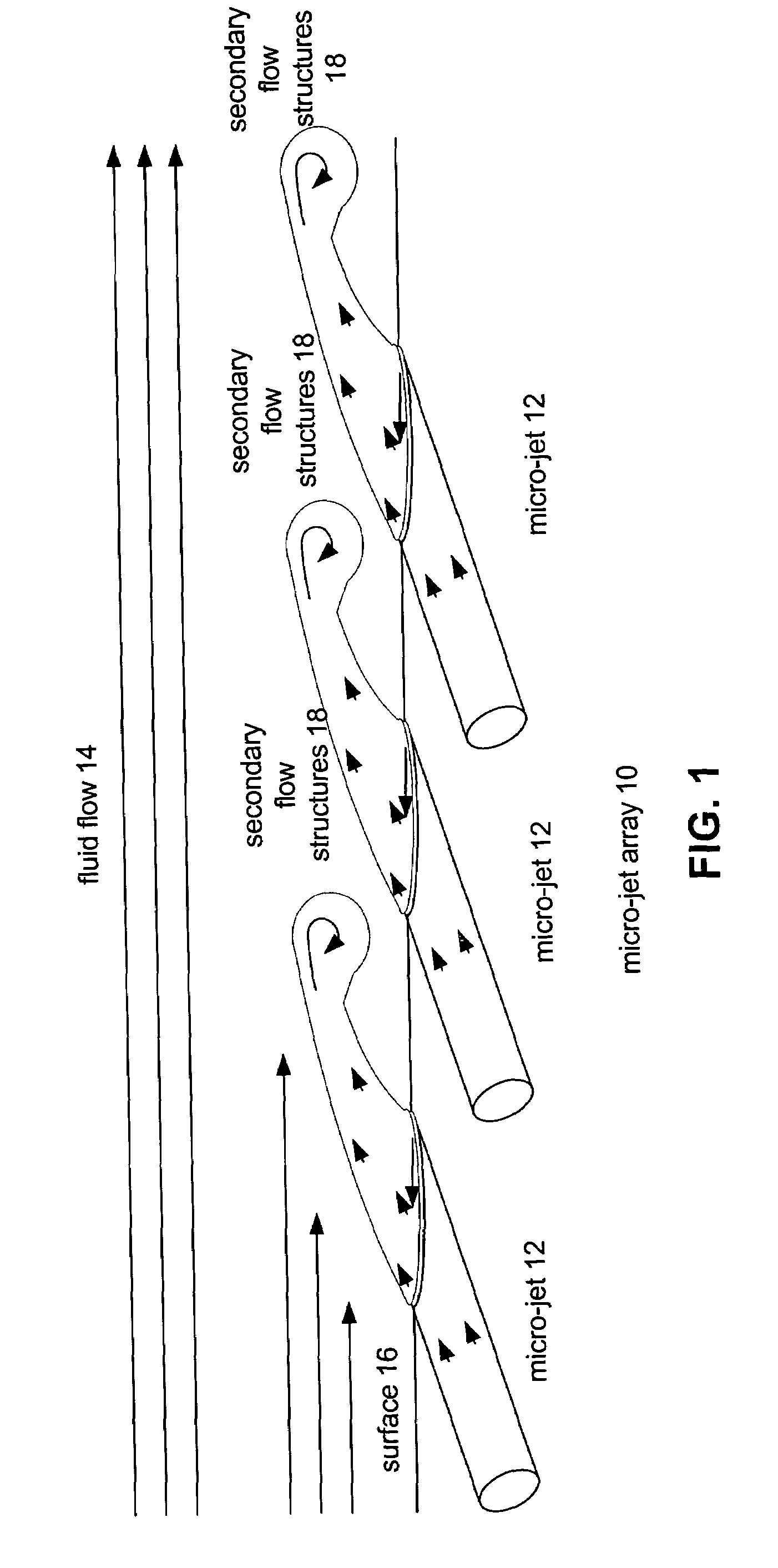
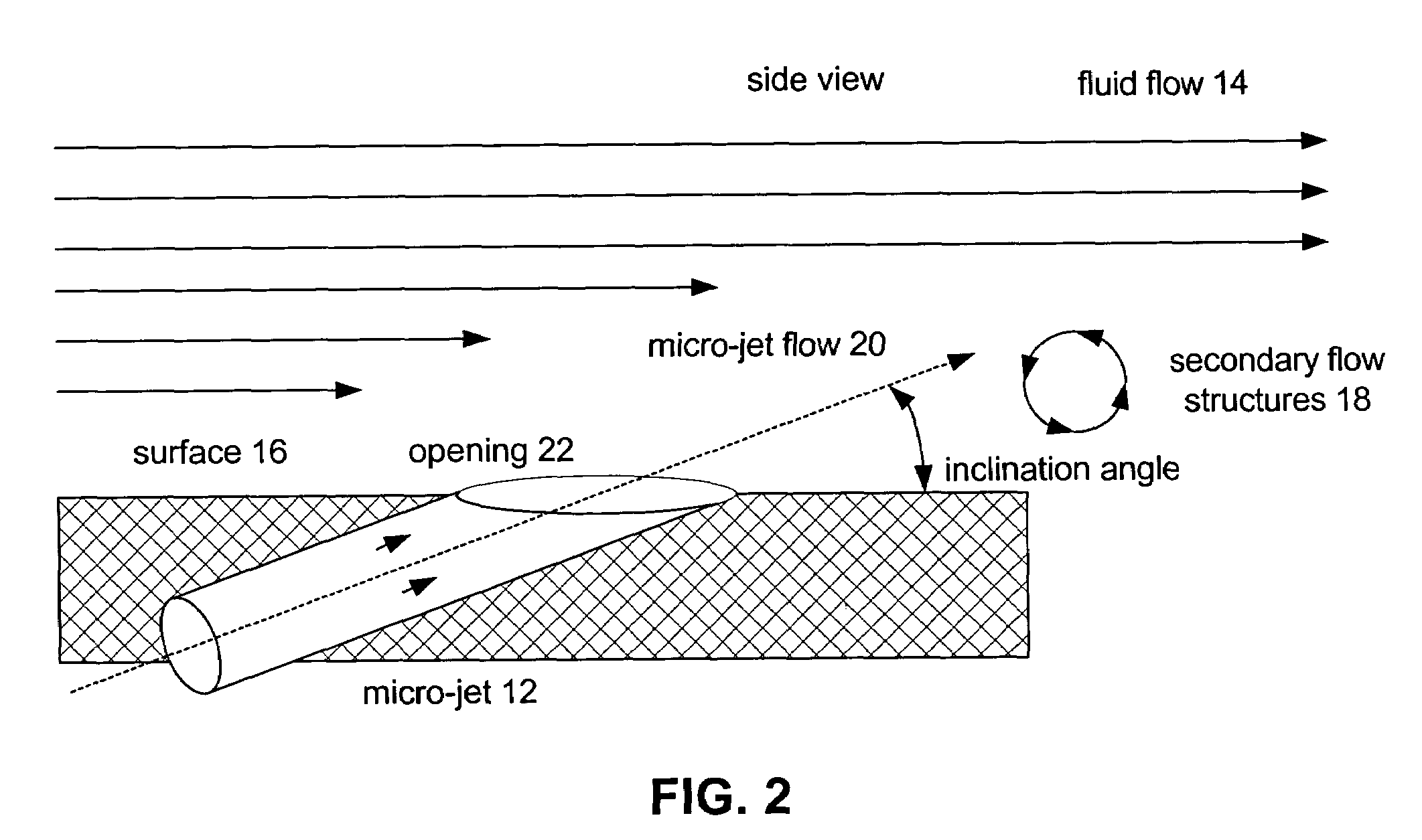
[0033]The present invention provides a system and method for manipulating aerodynamic or hydrodynamic fluid flow over a surface that substantially eliminates or reduces disadvantages and problems associated with previously developed systems and methods. More specifically, the present invention provides a system and method to prevent or minimize exposure of downstream components to buffeting or fatigue through the use of very-small-scale arrays of jets (micro-jets). This system and method includes the placement of micro jet arrays on surfaces bounding the fluid flow. These very-small-scale effectors manipulate the flow behavior of the fluid flow, influence the inception point, size, and trajectory of flow field vortices within the fluid flow, and reduce flow separation within the primary fluid flow.

[0034]FIG. 1 d...


PUM


Abstract

The present invention provides a system and method for actively manipulating and controlling aerodynamic or hydrodynamic flow field vortices within a fluid flow over a surface using micro-jet arrays. The system and method for actively manipulating and controlling the inception point, size and trajectory of flow field vortices within the fluid flow places micro-jet arrays on surfaces bounding the fluid flow. These micro-jet arrays are then actively manipulated to control the flow behavior of the ducted fluid flow, influence the inception point and trajectory of flow field vortices within the fluid flow, and reduce flow separation within the primary fluid flow.

Description

TECHNICAL FIELD OF THE INVENTION[0001]The present invention relates generally to manipulation of flow field vortices and more particularly, a system and method for manipulating the shedding, size, and trajectory flow field vortices from aerodynamic surfaces with an active array of micro-jets to reduce downstream buffeting and fatigue.BACKGROUND OF THE INVENTION[0002]Flow field vortices generated by fluid flow over aerodynamic surfaces can buffet and fatigue any downstream structure exposed to these vortices. Vortices can be generated at the fore body of an aircraft or other upstream structure, and damage control surfaces, engines, after body / empennage, nacelles, turrets, or other structures integrated into the airframe. Additionally, these vortices can be ingested within engine air intakes or other like air inlets leading to poor performance and / or stalling of the aircraft engines. Stalling the aircraft engine creates a potentially hazardous condition.[0003]Next generation aircraft,...

Claims


Application Information

Patent Timeline
Patent Type & Authority Patents(United States)
IPC IPC(8): B64C21/04
CPCB64C21/02Y02T50/166B64C2230/18Y02T50/10
Inventor MILLER, DANIEL N.TRUAX, PHILIP P.YAGLE, PATRICK J.
Owner LOCKHEED MARTIN CORP
Why Eureka
Try Eureka