Drive train

a technology of drive train and drive shaft, which is applied in the direction of couplings, rotary clutches, fluid couplings, etc., can solve the problems of limited maximum allowable temperature of control units, limited allowable limits, and detrimental to the availability of hydrodynamic machines, so as to shorten the lifetime of individual electronic components

Active Publication Date: 2009-05-05
VOITH PATENT GMBH
View PDF8 Cites 19 Cited by
  • Summary
  • Abstract
  • Description
  • Claims
  • Application Information

AI Technical Summary

Benefits of technology

[0021]The temperature of the control unit accordingly adjusts itself in accordance with a heat transfer from the control unit to the cooling medium of the vehicle or, during a so-called cold start, from the cooling medium to the control unit. The same holds true, in particular, for the control valves that are integrated with the control unit in a common control module and / or a common housing, for example. The temperature course of the control unit or of the control valves, respectively, is accordingly averaged out in comparison to conventional designs and this has a positive effect on the lifetime of the component parts used.

Problems solved by technology

In order to be able to fabricate the control unit at an economically practical cost from comparatively inexpensive materials, the maximum allowable temperature of the control unit is limited.
(under Arctic conditions, from −50° C.) to over 120° C. Because of this, the higher continuously allowed ambient temperatures result in limitations in the allowable maximum period of time that the electronic control unit of hydrodynamic machines may be turned on as well as, in particular, the control valves thereof, which are designed as solenoid valves, because the allowable temperature range for self-heating is correspondingly reduced by the difference of the higher ambient temperature with respect to the previously maximum allowable ambient temperature.
Such limitation of the operating time, for example, by a time-dependent switching on of the control unit and / or by a time-dependent actuation of the valves by way of an advance setting of defined time pauses between individual actuations or by way of pulse-width modulation, has a detrimental effect on the availability of the hydrodynamic machine and is accordingly undesirable.

Method used


Image

  • Drive train
  • Drive train
  • Drive train

Examples


Embodiment Construction

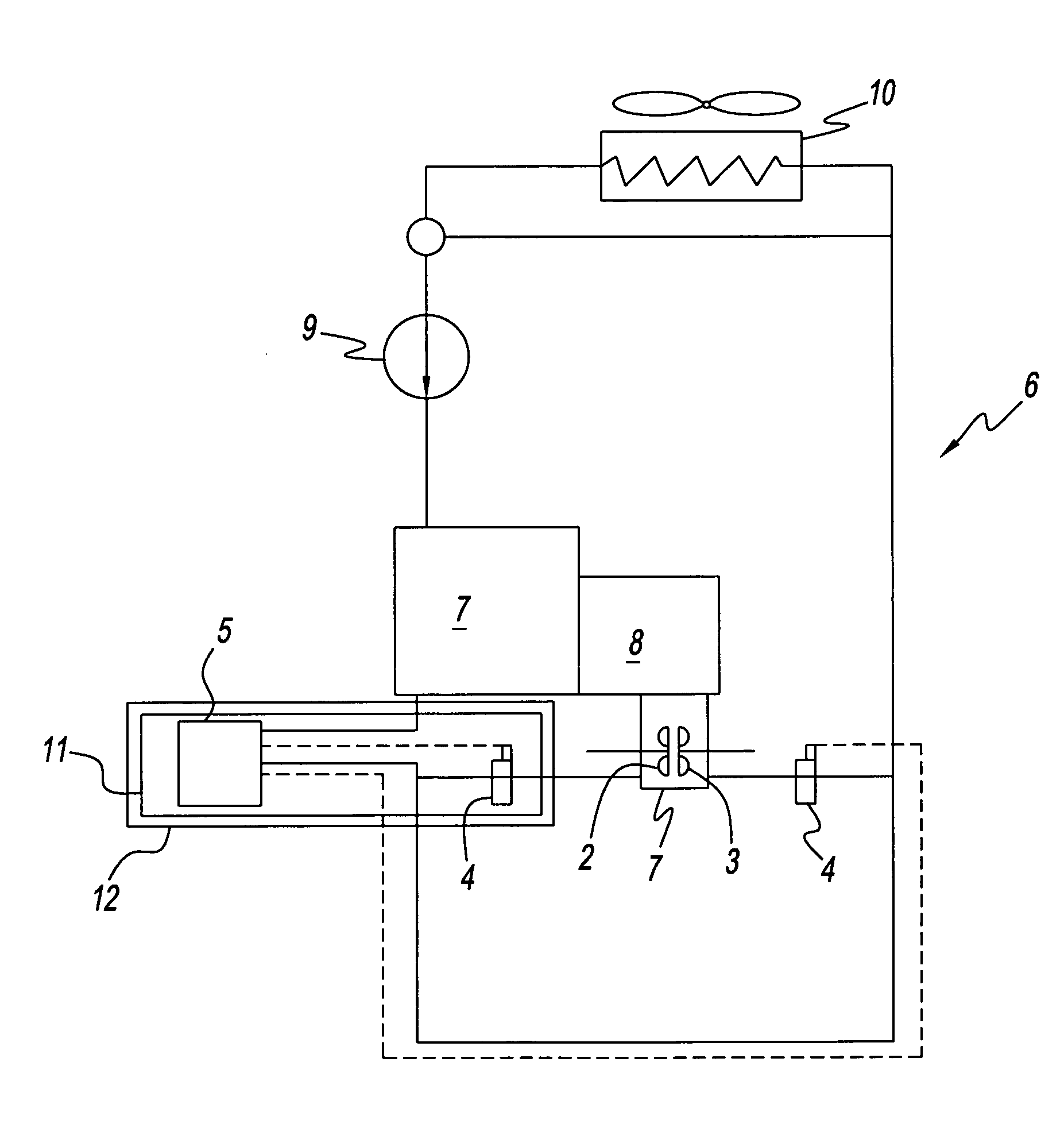
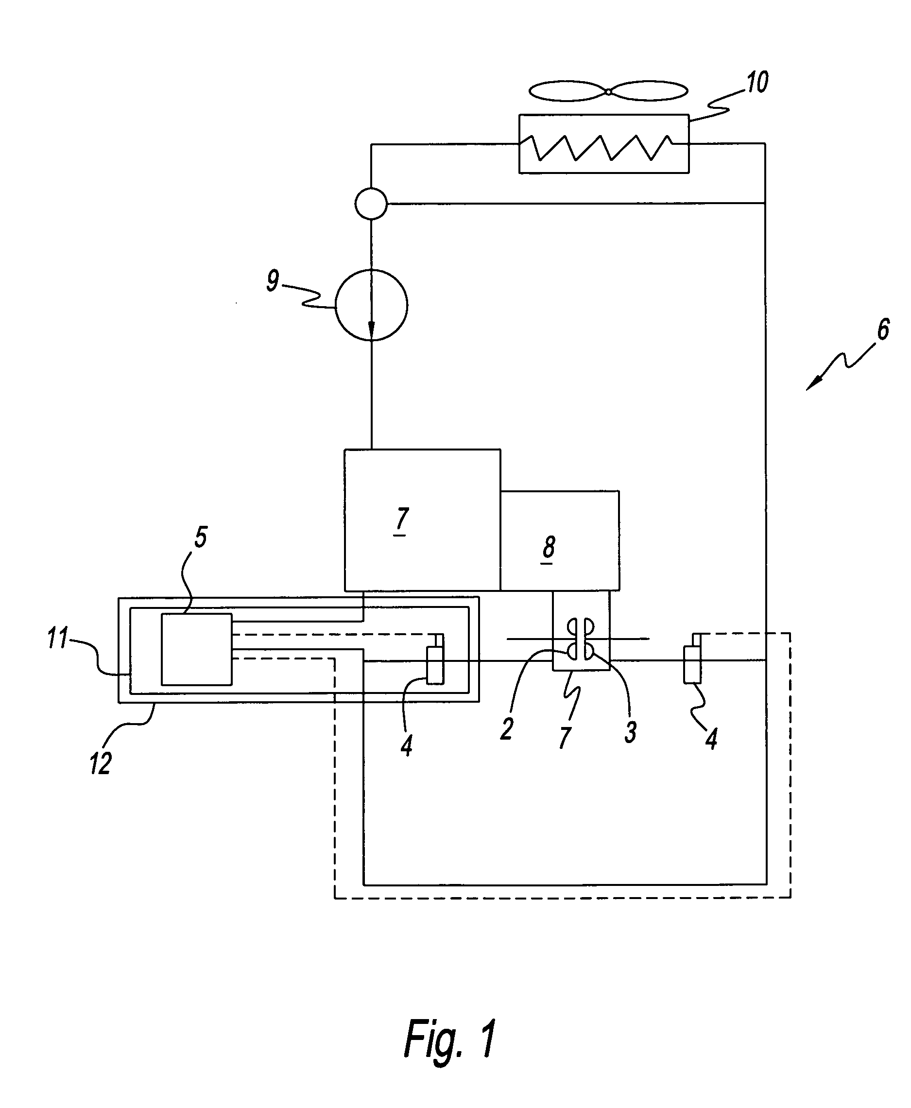
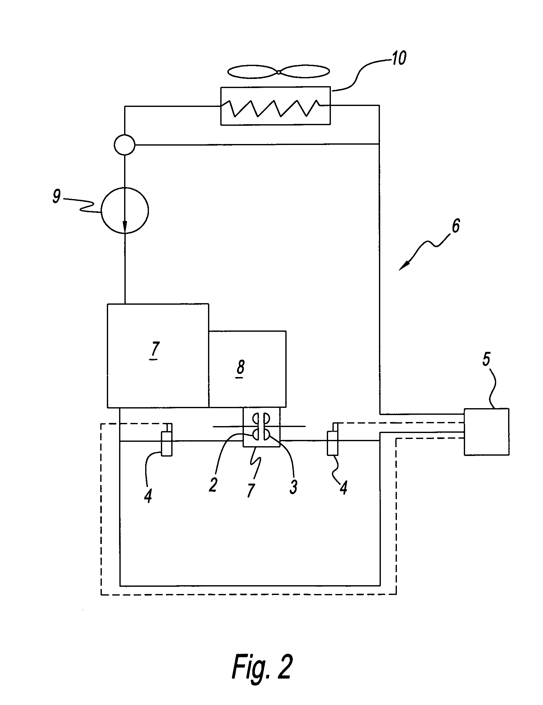
[0025]FIG. 1 shows various components of a motor vehicle drive train, namely, an internal combustion engine 7, which drives the driving wheels of a motor vehicle (not depicted) via a gearbox 8 connected thereto. Connected to the gearbox 8 in driven connection with the engine 7 is the hydrodynamic machine 1, which, here, takes the form of a hydrodynamic retarder and which has a primary impeller 2 and a secondary impeller 3, which together form a toroidal working chamber that can be filled with the cooling medium of the cooling medium circuit 6, which is at the same time the working medium of the hydrodynamic machine 1, in order to brake the motor vehicle without any wear.

[0026]The cooling medium, here water or a water mixture, of the cooling medium circuit 6 is circulated by means of a water pump 9 and, in the braking operation, of the hydrodynamic machine 1, additionally flows around the latter in the cooling medium circuit 6. The heat is dissipated from the cooling medium into the ...


PUM


Abstract

A drive train having a hydrodynamic machine and a cooling medium circuit with a liquid or gaseous cooling medium. The hydrodynamic machine has at least one primary impeller, a secondary impeller, at least one control valve, and a control unit. The control unit actuates the at least one control valve in order to control the flow of the working medium into or out of the hydrodynamic machine. The secondary impeller and the at least one primary impeller form a working chamber that can be filled with a working medium. The cooling medium circuit is configured to cool the working medium and the control unit.

Description

CROSS-REFERENCE TO RELATED APPLICATIONS[0001]This application claims the benefit under 35 U.S.C. §119(a) of German Application Serial No. 10 2005 037 640.1, filed Aug. 5, 2005, the entire contents of which are incorporated by reference herein.BACKGROUND OF THE INVENTION[0002]1. Field of the Invention[0003]The invention relates to a drive train, particularly a vehicle drive train, which has a hydrodynamic machine and a cooling medium circuit, the cooling medium being at the same time the working medium of the hydrodynamic machine.[0004]2. Description of Related Art[0005]Drive trains, particularly motor vehicle drive trains having hydrodynamic machines are known in a plurality of designs. For example, hydrodynamic brakes, so-called retarders, are used nowadays in heavy-duty motor vehicles for wear-free braking of the vehicle.[0006]Such hydrodynamic machines, particularly retarders, have a working chamber, which can be filled with a working medium in order to transmit torque or driving...

Claims


Application Information

Patent Timeline
Patent Type & Authority Patents(United States)
IPC IPC(8): F16D33/06
CPCB60T10/02F16D33/18F16D48/066F16D57/00F16D2300/021F16D2500/10487
Inventor SCHERER, ROLANDBISCHOFF, MARKUS
Owner VOITH PATENT GMBH
Why Eureka
Try Eureka