
Sliding safety structure for power supply receptacles

a safety structure and power supply technology, applied in the direction of live contact access prevention, electrical equipment, coupling device connection, etc., can solve the problems of life or property damage dangers, especially serious concerns for houses with babies or small children, and dangerous actions

Inactive Publication Date: 2009-05-05
XYZ SCI CO LTD
View PDF6 Cites 84 Cited by
  • Summary
  • Abstract
  • Description
  • Claims
  • Application Information

AI Technical Summary

Benefits of technology

[0005]The primary object of the present invention is to solve the aforesaid disadvantages by providing a safety structure for power supply receptacles that has a detent plate located in a receptacle to block slots thereof and remains at a lower side of the slots even if it is subject to a one side or uneven force.
[0007]The structure thus formed can provide enhanced safety protection for the power supply receptacle.

Problems solved by technology

Due to electricity is invisible to human eyes, electric shock or leakage resulted from users' negligence could cause hazards to people' life or property damage.
This concern is especially serious for houses which have babies or small children.
Hence safety use of electric power is an important issue that needs more attention.
It is a dangerous action that has to be guarded against constantly.
Hence protection effect is compromised.
While such a latch structure in Patent No. 337384 can prevent the safety detent plate from being moved away by an one side or uneven force, the latch relationship between the flange and notch cannot withstand too much of applying force, or movement of the safety detent plate still could happen and result in compromising of safety protection.
Therefore, Patent No. 337384 can not provide safe measures efficiently.

Method used


Image

  • Sliding safety structure for power supply receptacles
  • Sliding safety structure for power supply receptacles
  • Sliding safety structure for power supply receptacles

Examples


Embodiment Construction

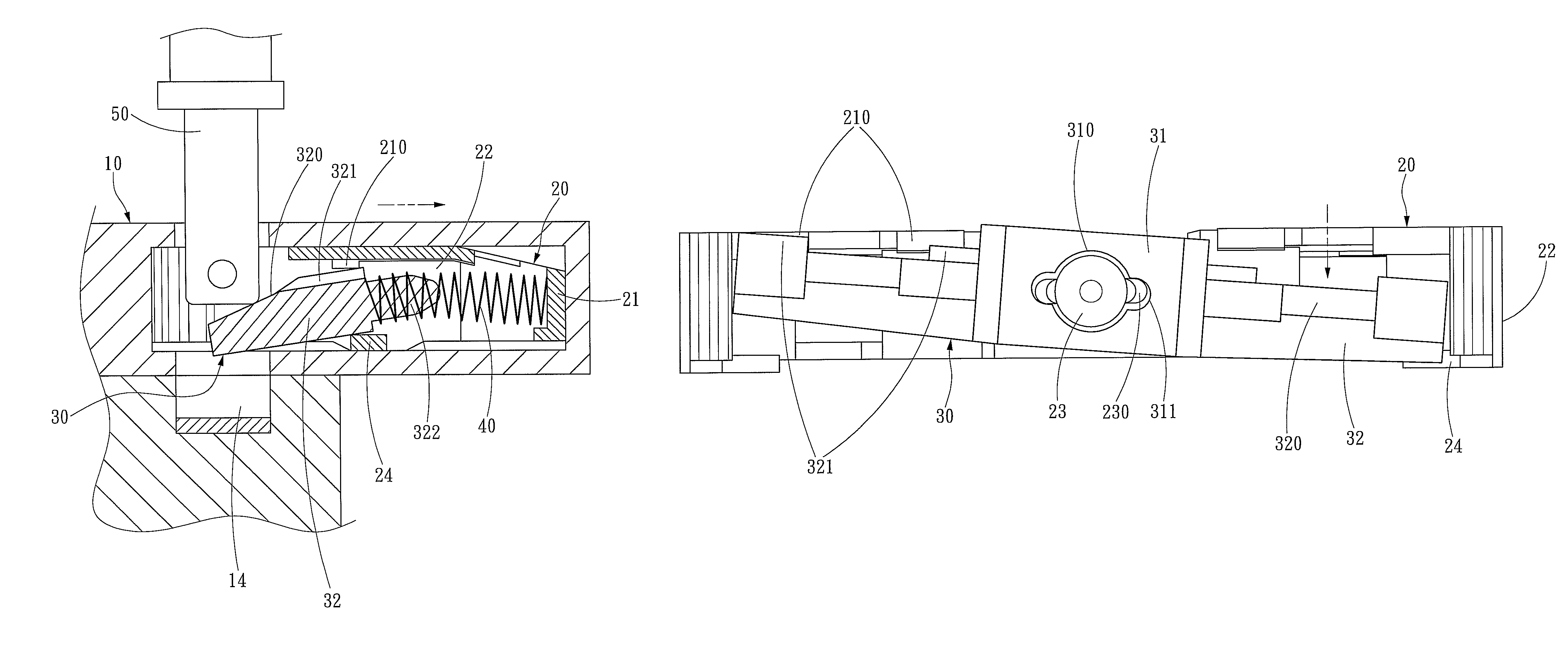
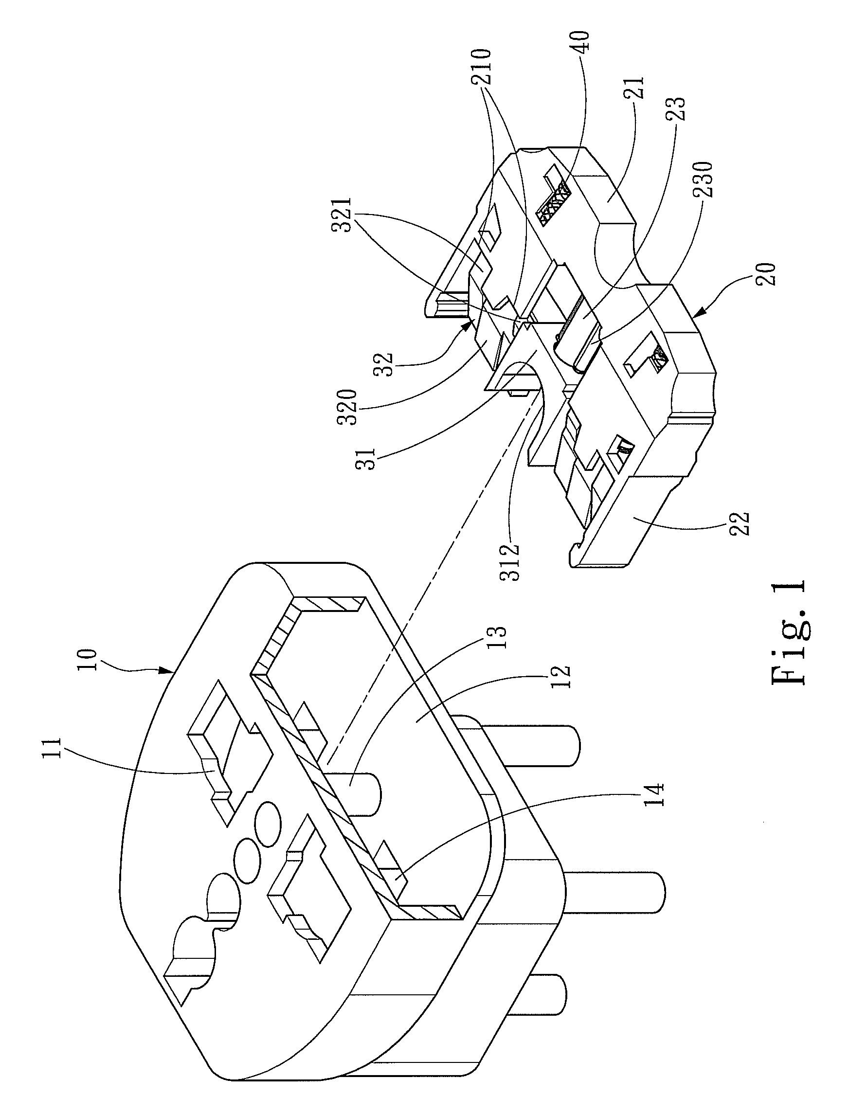
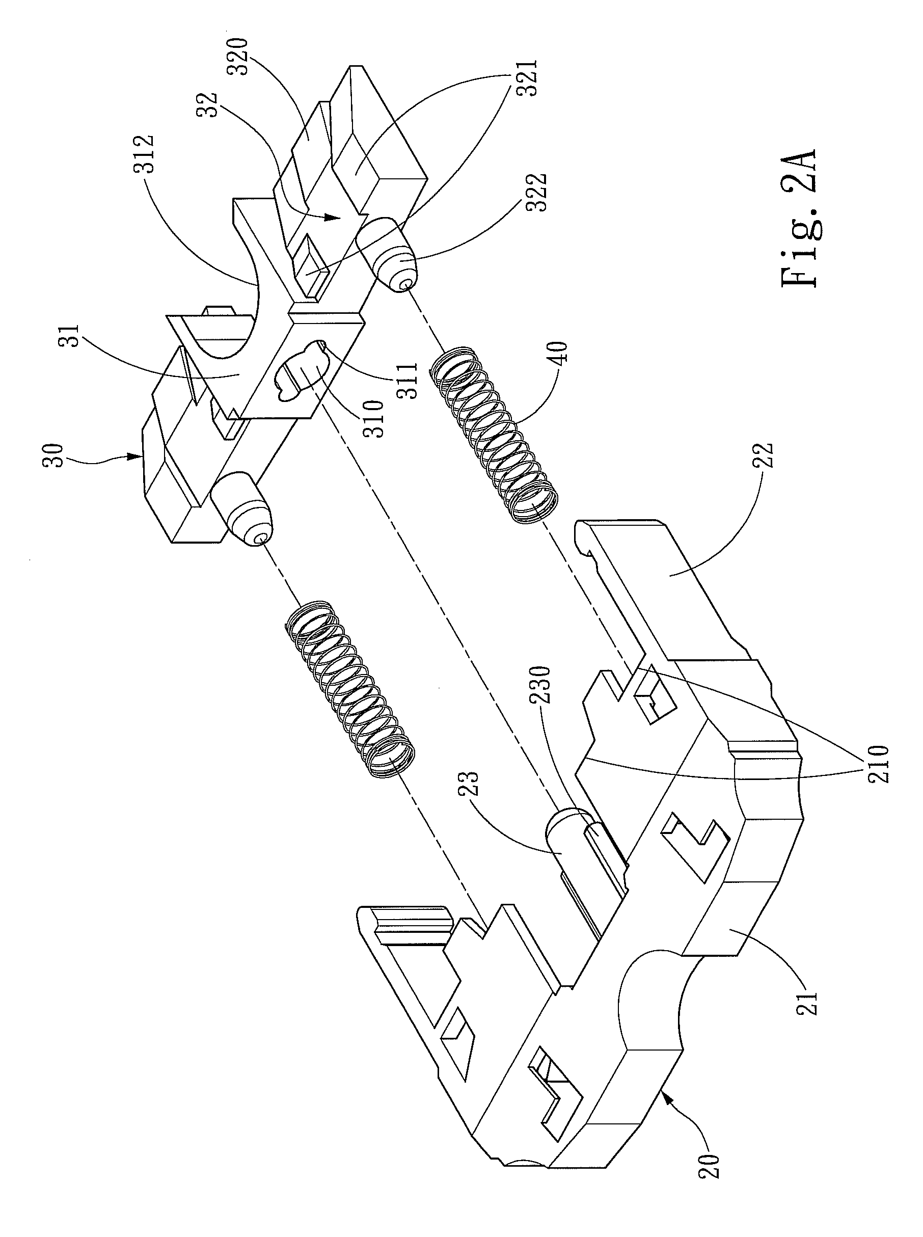
[0016]Please referring to FIGS. 1, 2A and 2B, the sliding safety structure for power supply receptacles according to the invention is located on an insertion path of a plug prong 50 (as shown in FIG. 3A) inserting to a receptacle electrode 14. It mainly includes a control dock 20 located on a loading surface 12 in a power supply receptacle 10 and a safety gate 30. The control dock 20 and the safety gate 30 are pushed by two ends of an elastic element 40 interposed between them. The control dock 20 has a base 21 and two bracing arms 22 at two sides of the base 21, and the base 21 has a directing stem 23 located between the two bracing arms 22. The safety gate 30 has a sliding portion 31 with a directing hole 310 formed thereon to be slidably coupled on the directing stem 23. The directing stem 23 and the directing hole 310 have respectively a directing flange 230 and a directing trough 311 corresponding to each other to increase the loading capability of the directing stem 23, and al...


PUM


Abstract

A sliding safety structure for power supply receptacles located on a path of a plug prong inserting to a receptacle electrode includes a control dock which has a directing stem, a safety gate slidably located on the directing stem and an elastic element which has two ends pushing respectively the control dock and the safety gate. The safety gate has two force receiving portions which are pushed by the elastic element in regular conditions to block the path of the plug prong inserting to the receptacle electrode and maintain at a latched position. When the plug prong is inserted into the receptacle, the two force receiving portions are depressed by the plug prong to move the safety gate to slide away from the latched position so that insertion of the plug prong to the electrode of the power supply receptacle is allowed. The safety gate also has a stopper below the sliding path thereof to harness the safety gate at the latched position when the two force receiving portions receive uneven forces. Thus an enhanced safety effect can be accomplished to improve the disadvantage occurred to the conventional safety structure which is openable when subject to a force at one side.

Description

FIELD OF THE INVENTION[0001]The present invention relates to a sliding safety structure and particularly to a safety structure adopted for using on power supply receptacles.BACKGROUND OF THE INVENTION[0002]Electric power is a convenient and steady energy source for modern households. Due to electricity is invisible to human eyes, electric shock or leakage resulted from users' negligence could cause hazards to people' life or property damage. This concern is especially serious for houses which have babies or small children. Hence safety use of electric power is an important issue that needs more attention. Most houses have power supply receptacles installed on lower locations of the walls. Children often have a great curiosity and try to insert metallic articles into the receptacles that are electric power-enabled. It is a dangerous action that has to be guarded against constantly.[0003]To prevent the risky situation mentioned above from happening, some techniques have been proposed....

Claims


Application Information

Patent Timeline
IPC IPC(8): H01R13/44
CPCH01R13/4534
Inventor LEE, CHIU-SANLEE, YI-HSUN
Owner XYZ SCI CO LTD
Learn More