Electrical connector with improved housing

a technology of electric connectors and housings, applied in the direction of coupling devices, two-part coupling devices, electrical apparatus, etc., can solve the problems of easy breakage of ribs with long distances, and achieve the effect of improving the housing

Inactive Publication Date: 2009-05-19
HON HAI PRECISION IND CO LTD
View PDF34 Cites 11 Cited by
  • Summary
  • Abstract
  • Description
  • Claims
  • Application Information

AI Technical Summary

Benefits of technology

[0006]An object of the present invention is to provide an electrical connector with an improved housing.

Problems solved by technology

However, the ribs with long distance are easy to break down during moulding procedure of the housing.

Method used


Image

  • Electrical connector with improved housing
  • Electrical connector with improved housing
  • Electrical connector with improved housing

Examples


Embodiment Construction

[0018]Reference will now be made to the drawing figures to describe the preferred embodiment of the present invention in detail.

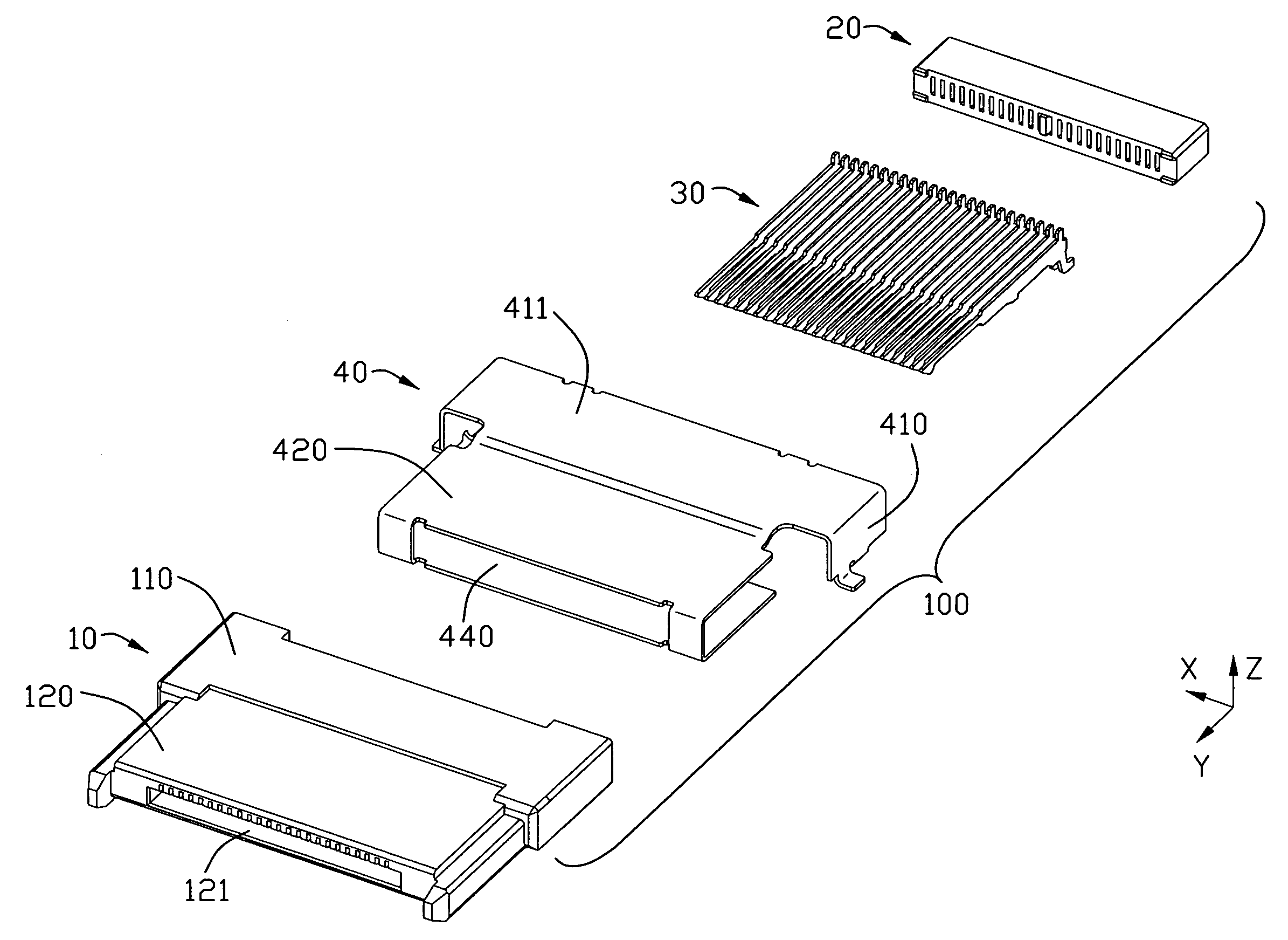
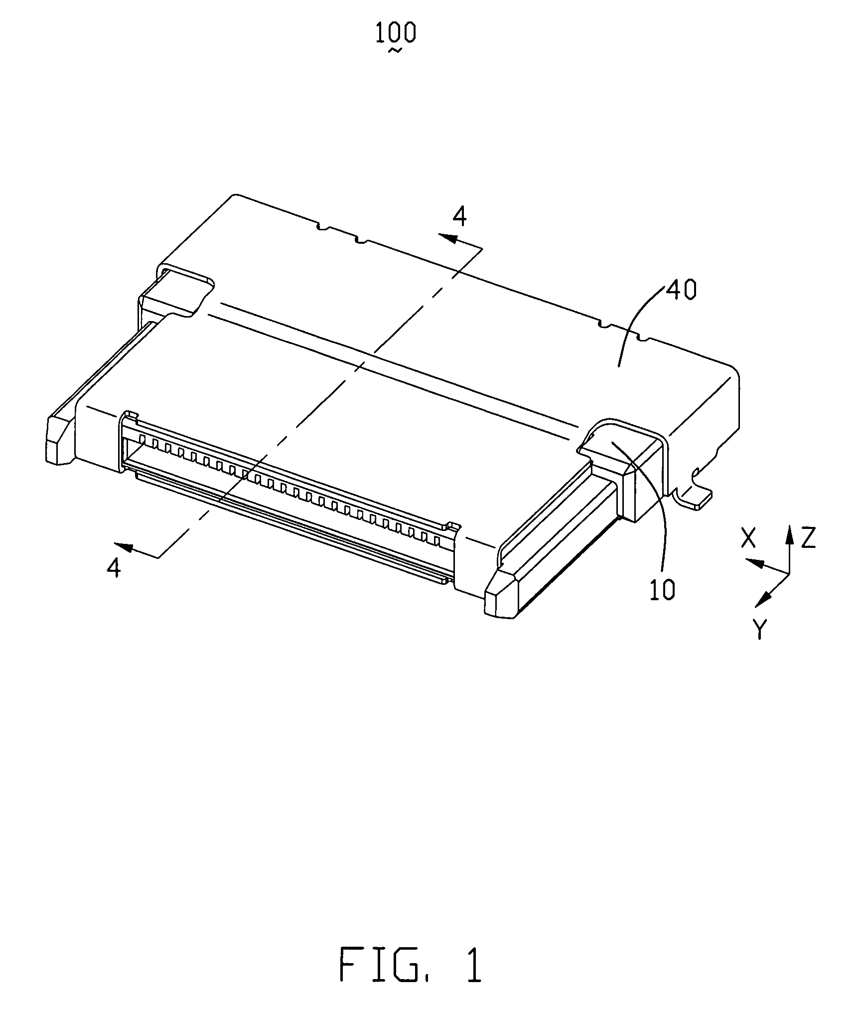
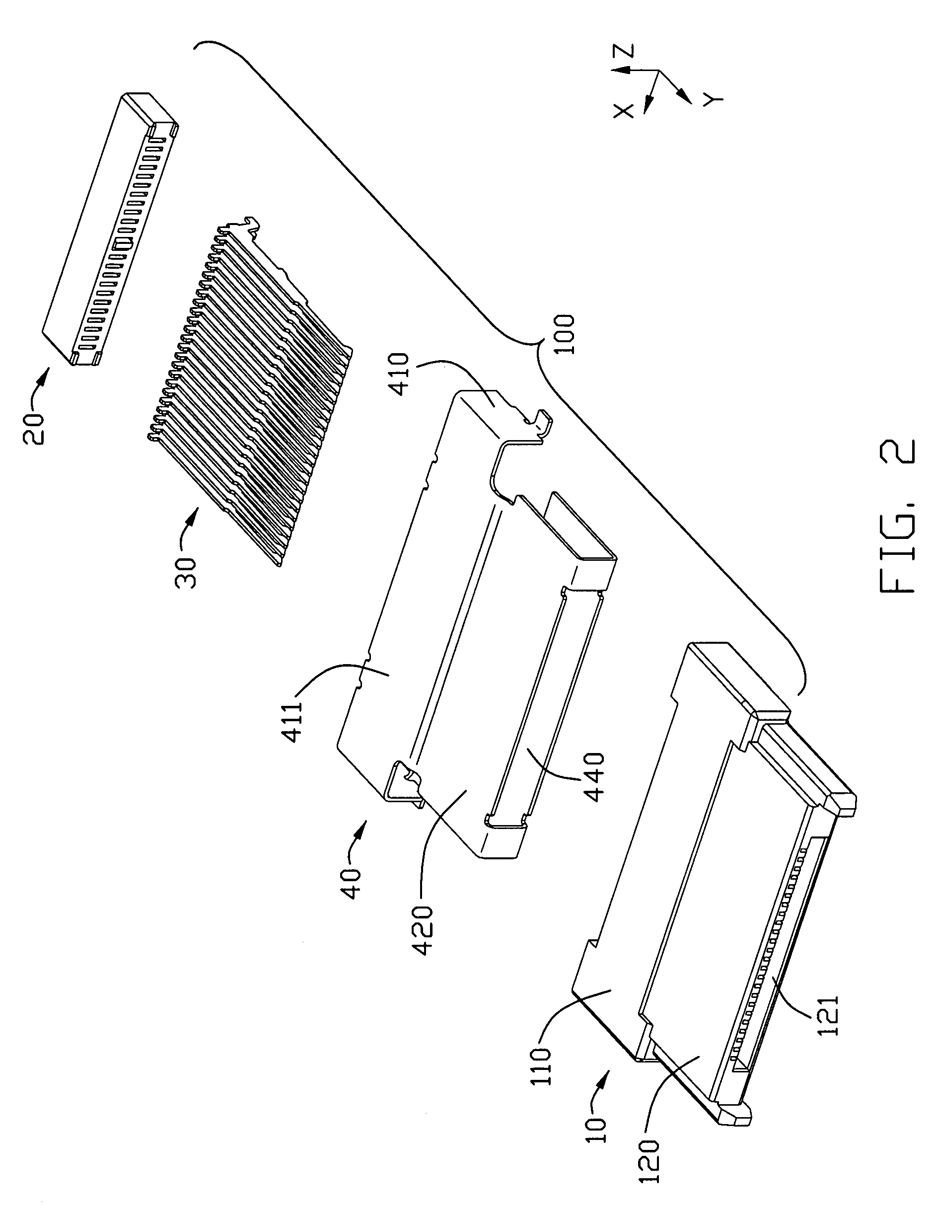
[0019]Referring to FIGS. 1 and 2, an electrical connector 100 comprises a first insulative housing 10, a second insulative housing 20, a plurality of terminals 30 and a shell 40 surrounding the first and the second insulative housing.

[0020]As shown in FIG. 2, the first insulative housing 10 comprises a base section 110 extending along a first direction (“X” direction). The base section 110 defines a front end and a rear end in a second direction (“Y” direction) vertical to the X direction. A mating section 120 extends forward from the base section. The mating section 120 defines a mating cavity 121 in the front portion thereof for receiving a mating connector (not shown). See FIGS. 5 and 6, a plurality of terminal grooves 130 runs through the insulative housing in the Y direction, which is arranged parallel and spaced along the X direction with predetermine...


PUM


Abstract

An electrical connector (100) comprises a first insulative housing (10) comprising a base section (110) extending along a first direction and defining a front end and a rear end thereof in a second direction vertical to the first direction. A mating section (120) extends forward from the front end of the base section in the second direction and a mating cavity (121) is defined in the mating section and opened forward. A receiving chamber (140) is provided in the rear end of the base section (110) and opened rearward. A plurality of terminal grooves (130) is arranged along the first direction and extends along the second direction. A second insulative housing (20) is received and retained in the receiving chamber (140) of the first insulative housing (10) with a plurality of passageways (210) corresponding with and aligning with said terminal grooves (130) in the second direction. A plurality of terminals (30) is retained in the terminal grooves and the passageways.

Description

BACKGROUND OF THE INVENTION[0001]1. Field of the Invention[0002]The present invention relates to an electrical connector which comprises a first and a second housing.[0003]2. Description of Related Art[0004]A conventional electrical connector 10′ is introduced referring to FIGS. 8 and 9, which comprises an insulative housing 1′ with a plurality of terminals 2′ mounted thereon and a shield 3′ surrounding the insulative housing. The insulative housing comprises a base section and a mating section extending forward from the base section and defining a receiving space 11′ therein. Each terminal 2 comprises a contacting portion exposed to the receiving space and a solder portion projecting out of the insulative housing.[0005]FIG. 9 is a cross-sectional view of FIG. 8 taken along line 9-9, which discloses an inner structure of the insulative housing. The insulative housing defines a plurality of grooves 12′ extending forward from a rear side of the base section until communicating with th...

Claims


Application Information

Patent Timeline
Patent Type & Authority Patents(United States)
IPC IPC(8): H01R13/514
CPCH01R12/712H01R23/6873H01R13/658
Inventor SHEN, GUO-JIANZHANG, JUN-JIANLI, REN-CHIH
Owner HON HAI PRECISION IND CO LTD
Why Eureka
Try Eureka