Connector

a technology of connecting rods and connectors, applied in the direction of incorrect coupling prevention, coupling device connection, electrical apparatus, etc., can solve the problems of insufficient connection, lock arm resilient deformation, insufficient connection, etc., and achieve the effect of preventing insufficient connection

Inactive Publication Date: 2002-09-12
SUMITOMO WIRING SYST LTD
View PDF0 Cites 3 Cited by
  • Summary
  • Abstract
  • Description
  • Claims
  • Application Information

AI Technical Summary

Benefits of technology

[0009] The invention relates to a connector with a housing for accommodating at least one terminal fitting. A resiliently deformable lock arm is formed separately from the housing and is adapted to lock the connector and a mating connector together. At least one biasing member is provided for biasing the lock arm toward a usual or front position along a connection direction with the mating connector. An insufficient connection preventing portion and a press-preventing portion are provided on the housing. The press-preventing portion prevents the lock arm from being pressed when the lock arm is at the usual position. Accordingly, the connectors cannot be connected by mistakenly pressing the lock arm and causing the lock arm to undergo a resilient deformation. Thus, insufficient connection can be prevented more securely.
[0013] The lock arm may be disposed in a mounting groove in the housing and the press-preventing portion may bridge the opposite lateral edges of the mounting groove. Accordingly, the press-preventing portion strengthens the housing.

Problems solved by technology

Accordingly, the connectors cannot be connected by mistakenly pressing the lock arm and causing the lock arm to undergo a resilient deformation.
Thus, insufficient connection can be prevented more securely.

Method used


Image

  • Connector
  • Connector
  • Connector

Examples


Embodiment Construction

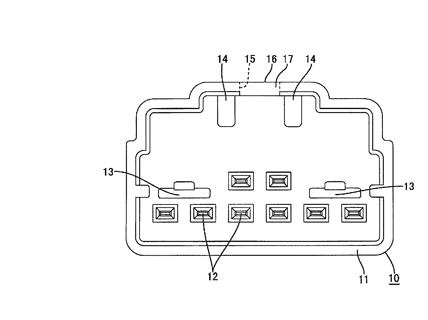
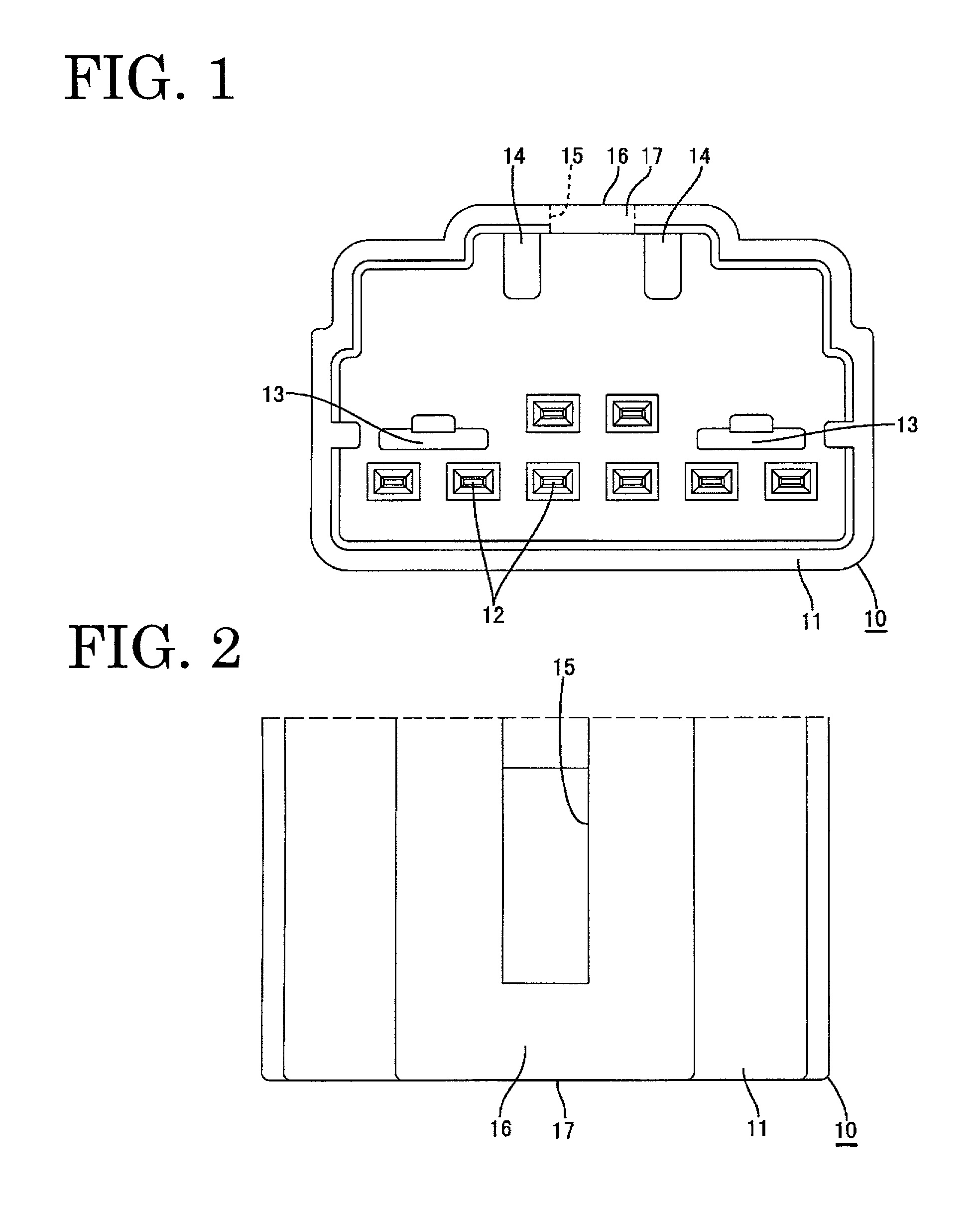
[0036] A mating connector is identified by the numeral 10 in FIGS. 1, 2 and 6, and is coupled directly to a piece of equipment as shown in FIG. 6. The mating connector 10 has a receptacle 11 with an open front. Eight male terminal fittings 12 project into the receptacle in upper and lower stages. More particularly, two terminal fittings 12 are disposed in a widthwise center of the mating connector 10 in the upper stage and six male terminal fittings 12 are disposed in the lower stage. Shorted state canceling pieces 13 project into the receptacle 11 at the left and right sides of the upper stage male terminal fittings 12. Left and right guide ribs 14 project inwardly from the ceiling surface of the receptacle 11, and an engaging groove 15 extends back between the left and right guide ribs 14 in the upper wall of the receptacle 11.

[0037] The receptacle 11 of the male connector 10 is dimensioned to receive at least portions of a housing 18 of a female connector 20, as shown in FIGS. 3-...


PUM


Abstract

A connector (20) has a housing (18) for accommodating female terminal fittings (22). A resiliently deformable lock arm (46) is formed separately from the housing (18) and is adapted to lock the connector (20) to a mating connector (10). Coil springs (40) bias the lock arm (46) forwardly to a usual position. Insufficient connection preventing portions (34) project from the housing (18) toward the lock arm (46) and the lock arm (46) is provided with stroke guides (51). The stroke guides (51) move onto the insufficient connection preventing portions (34) during connection of the connectors (10, 20). The housing (18) also has an arched press-preventing portion (32) for preventing the lock arm (46) from being pressed from above when the lock arm (46) is at the usual position.

Description

BACKGROUND OF THE INVENTION[0001] 1. Field of the Invention[0002] The present invention relates to a connector.[0003] 2. Description of the Related Art[0004] A known connector is identified by the numeral 100 in FIG. 18, and has a lock arm 101 with a locking projection 101A. The connector 100 also has a housing 102 that is formed separately from the lock arm 101. Insufficient connection preventing portions 103 are formed on the housing 102, and stroke guides 104 project from opposite sides of the lock arm 101 at locations near the insufficient connection preventing portions 103. A biasing member (not shown) urges the lock arm 101 forwardly and into a position where the stroke guides 104 are forward of the insufficient connection preventing portions 103.[0005] The connector 100 can be mated with a mating connector 105. During this connection, the front surface 106 of the mating connector 105 engages the locking projection 101A and pushes the lock arm 101 rearward or to the right in F...

Claims


Application Information

Patent Timeline
Patent Type & Authority Applications(United States)
IPC IPC(8): H01R13/64H01R13/627H01R13/635H01R13/703
CPCH01R13/6272H01R13/635H01R13/7032
Inventor SAKA, YUKINORIOKUTANI, KOJI
Owner SUMITOMO WIRING SYST LTD
Why Eureka
Try Eureka