Electrical connector with contact terminals isolated from each other within the housing

Inactive Publication Date: 2009-08-25
HON HAI PRECISION IND CO LTD
View PDF14 Cites 2 Cited by
  • Summary
  • Abstract
  • Description
  • Claims
  • Application Information

AI Technical Summary

Benefits of technology

[0006]It is an object of the present invention to provide an electrical connector with an improved housing which isolates conductive terminals therein.

Problems solved by technology

However, the tails of the terminals are arranged in cantilevered form and are critical before the wire management member is mounted on the connector housing.

Method used


Image

  • Electrical connector with contact terminals isolated from each other within the housing
  • Electrical connector with contact terminals isolated from each other within the housing
  • Electrical connector with contact terminals isolated from each other within the housing

Examples


Embodiment Construction

[0014]Reference will now be made in detail to the preferred embodiment of the present invention.

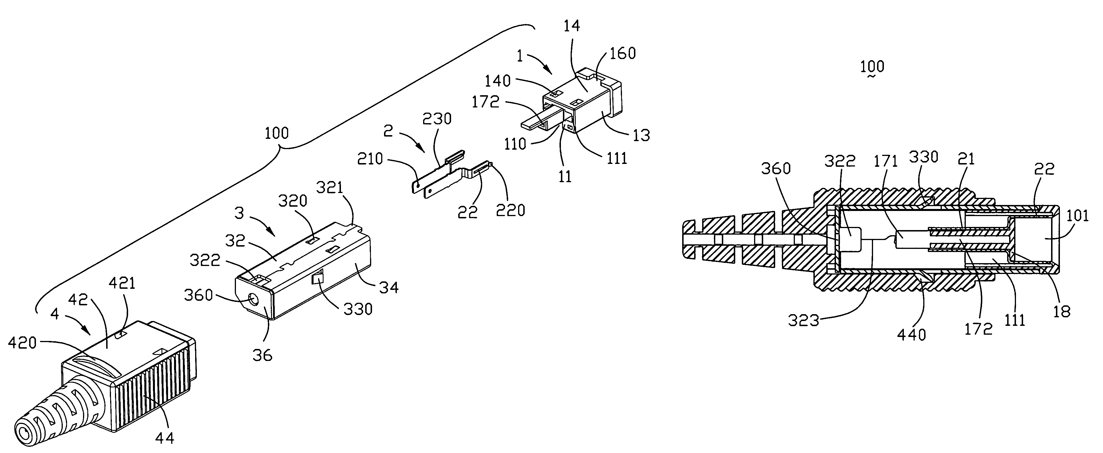
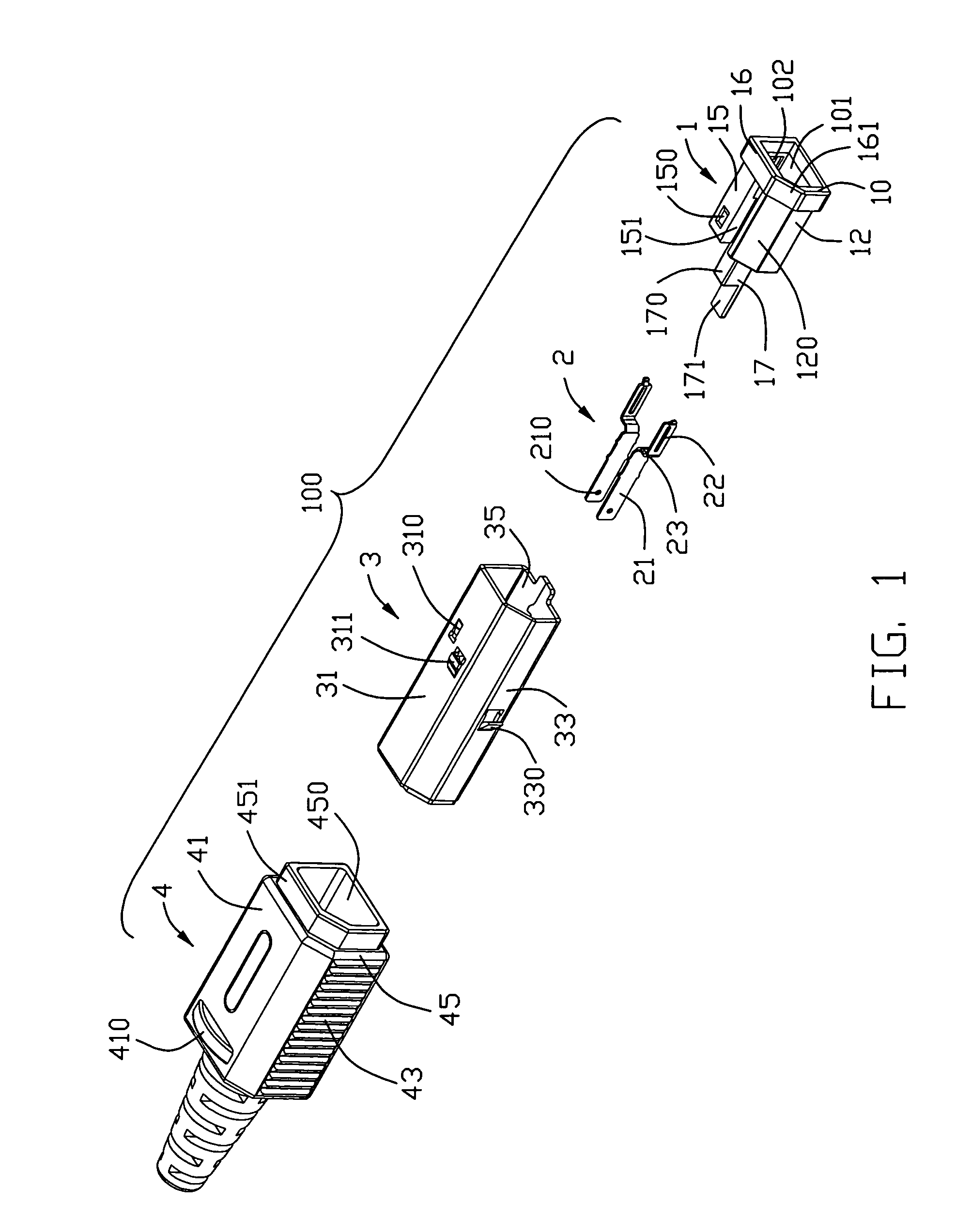
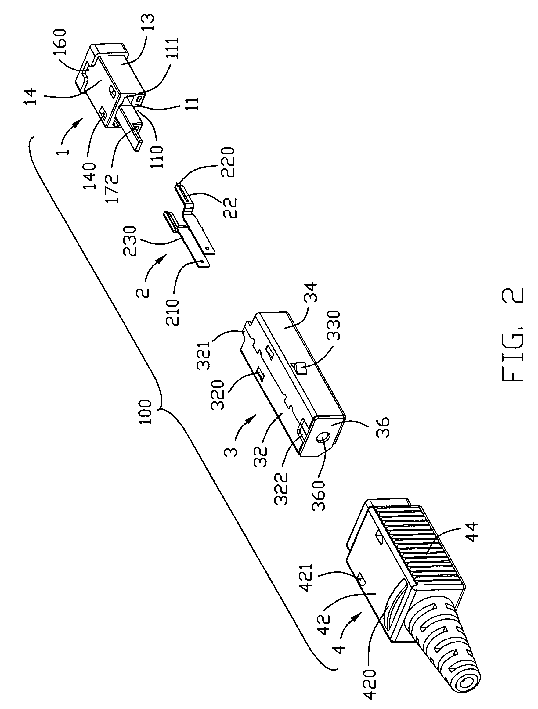
[0015]Please referring to FIGS. 1-4, a power connector 100 according to the present invention comprises an insulative housing 1, a pair of conductive terminals 2 disposed in the housing 1, a conductive shell 3 partially covering the housing 1 and an insulative casing 4 located at the outermost.

[0016]Please referring to FIGS. 1-2, the housing 1 defines a front portion 10, a rear portion 11, a pair of sidewalls 12, 13, and top and bottom walls 15 and 14. The front portion 10 stands at the front of the housing 1 and comprises an annular enlargement portion 16 which has a notch 160 and an inclined surface 161. The rear portion 11 forms a step portion 17 at the rear thereof, the rear portion 17 having a projection 170 and a supporting plate 171 extending backwards from a lower end of the projection 170 for supporting a cable (not shown). The projection 170 forms at the center thereof a cavity ...


PUM


Abstract

An electrical connector (100) according to the present invention includes an insulative housing (1) and a pair of conductive terminals (2). The housing includes a wire connecting portion (11) for connecting a wire and a mating port (10) with a receiving space (101) at the center thereof adapted for receiving a complementary connector, and the wire connecting portion defines a plurality of surfaces. The pair of conductive terminals include mating portions (22) received in the receiving space and soldering portions (21) surface mounted on different surfaces of the wire connecting portion of the housing so that the soldering portion of the terminals is separated by the wire connecting portion of the housing.

Description

BACKGROUND OF THE INVENTION[0001]1. Field of the Invention[0002]This invention generally relates to an electrical connector, and more particularly, to an electrical connector with contact terminals isolated from each other within the housing.[0003]2. Description of the Prior Art[0004]U.S. Pat. No. 6,802,744 discloses an electrical connector which includes a connector housing, a cable and a plurality of terminals. The terminals are held in the connector housing and each comprises a tail which extends out the connector housing to be soldered to the cable. A wire management member is joint to the connector housing to support the tails of terminals. However, the tails of the terminals are arranged in cantilevered form and are critical before the wire management member is mounted on the connector housing. Moreover, the connector housing has to be wide enough to array the plurality of the terminals in a row.[0005]Hence, an improved electrical connector is desired to overcome the above pro...

Claims


Application Information

Patent Timeline
Patent Type & Authority Patents(United States)
IPC IPC(8): H01R12/24
CPCH01R13/506H01R2103/00H01R24/28H01R13/5845
Inventor WANG, CHANG-YINCHENG, WEI-YA
Owner HON HAI PRECISION IND CO LTD
Why Eureka
Try Eureka