Seat

a seat and seat technology, applied in the field of seats, can solve the problems of passenger injury, passenger neck injury, passenger injury, etc., and achieve the effect of improving the holding ability of passengers and improving the safety of passengers

Inactive Publication Date: 2009-06-02
OGAWA TARO +2
View PDF5 Cites 14 Cited by
  • Summary
  • Abstract
  • Description
  • Claims
  • Application Information

AI Technical Summary

Benefits of technology

[0012]It is therefore an object of this invention to provide a seat that can restrain a rearward tilting of its backrest and absorb impact energy when a rear impact acts thereon.
[0015]As above, the rearward tilting of the inverse U shaped back frame can be restrained so as to prevent a passenger from sliding up, and thus, the seat according to this invention can improve the holding ability of passenger. In addition, the rearward tilting of the inverse U shaped back frame can be restrained, and thus, a rear space of this seat can be almost maintained so as to improve the safety of a passenger sat on a rear seat.

Problems solved by technology

If a rear impact due to an accidental collision and the like acts on an automobile that installs such a seat and then acts on a passenger sat on the seat, the passenger will be injured.
If a hard impact acts thereon, a backrest of the seat will be tilted rearward and the passenger will slide up along the backrest, and as a result, the passenger will suffers a serious injury.
That is, if there is no headrest, the passenger's head will be tilted (or rotated) rearward and the passenger's neck suffers a serious damage due to the rear impact.
However, disadvantageously, if the impact energy is larger, the backrest will be tilted rearward and the passenger will slide up such that the passenger's head rides over the headrest to injure in the passenger's neck and the passenger may be thrown out of the seat.
In addition, if the front seat is tilted rearward when a rear impact acts thereon, a rear space behind the front seat becomes smaller and a passenger sat on a rear seat will be injured.
Accordingly, in automotive industry, it is a technical problem to improve a passenger's safety when a rear impact acts on a seat.

Method used


Image

  • Seat
  • Seat
  • Seat

Examples


Embodiment Construction

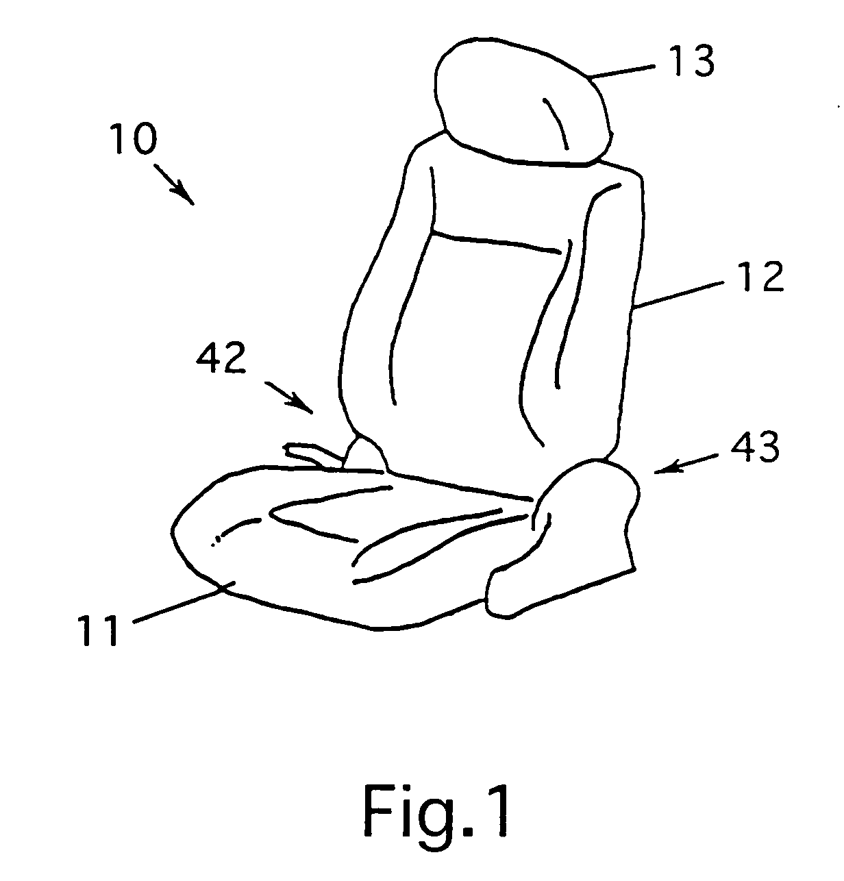
[0036]A seat according to this invention includes a seat part and a backrest as well as a seat shown in FIG. 1.

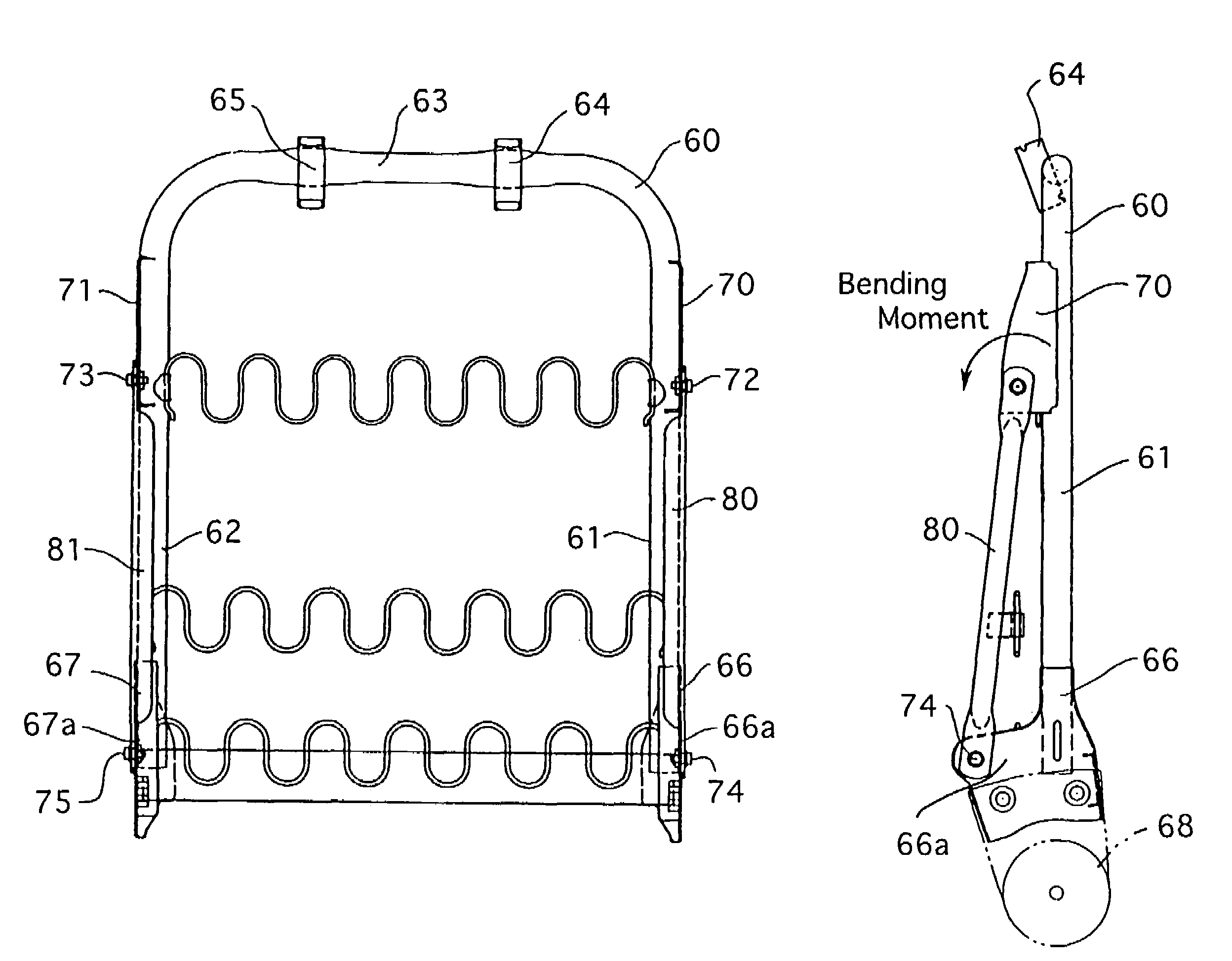
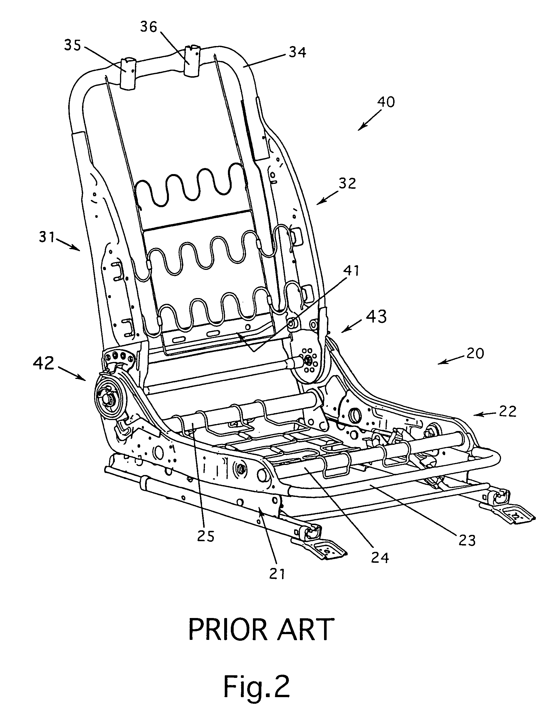
[0037]The seat according to this invention effectively restrains a rearward tilting of a back frame of the backrest when a rear impact acts on the seat and absorbs the impact energy mainly in the back frame. Thus, the characteristic of this invention is a frame structure of the backrest, as explained below, and the seat part as one component of the seat according to this invention is substantially the same as that of the prior art seat. (The seat part used in this invention comprises a pair of side supporting frame members that are connected with each other and a cushion attached on the side supporting frame members as shown in FIG. 2, as well as that of the prior art seat.) Therefore, the frame structure of the backrest of the seat according to this invention is explained in detail below.

[0038]FIG. 3 shows a perspective view of a frame structure of a backrest 50 according ...


PUM


Abstract

A seat according to this invention comprises a seat part and a backrest attached to a rear side of the seat part. The seat part comprises a cushion attached to a pair of side supporting frame members connected with each other. The backrest comprises a cushion attached to an inverse U shaped back frame. Each end of the inverse U shaped back frame is connected to each rear end of the side supporting frame members of the seat part. The inverse U shaped back frame comprises side supporting parts that are positioned in parallel and a top supporting part that connects top ends of the side supporting parts. Lower ends of side supporting parts are connected to rear ends of the side supporting frame members of the seat part via lower attaching parts, respectively. Each lower attaching part has an ear part that projects frontward. Supporting members connect between the side supporting parts and the ear parts of the lower attaching parts, respectively. According to this invention, a rearward tilting of its backrest can be restrained and absorb impact energy when a rear impact acts on the seat.

Description

BACKGROUND OF THE INVENTION[0001]This invention relates to a seat of a passenger vehicle such as an automobile. In particular, this invention relates to such a seat that considers its safety when a rear impact acts thereon.[0002]FIG. 1 shows a bucket seat typically installed in a passenger vehicle such as an automobile. The seat 10 comprises a seat part 11, a backrest 12 attached to the rear side of the seat part 11 and a headrest 13 attached to the top part of the backrest 12. The seat part 11 and the backrest 12 have cushions, respectively. The cushion of the backrest 12 supports a back of a passenger sat on the cushion of the seat part 11.[0003]FIG. 2 shows a conventional frame structure of a seat as shown in FIG. 1. As shown, the frame structure has a bottom frame 20 as a main frame of the seat part 11 and a back frame 40 as a main frame of the backrest 12.[0004]The bottom frame 20 has side supporting frame members 21, 22. One side supporting frame member 21 is positioned opposi...

Claims


Application Information

Patent Timeline
Patent Type & Authority Patents(United States)
IPC IPC(8): B60N2/42
CPCB60N2/4228B60N2/42709B60N2/42745
Inventor OGAWA, TAROKOMATSUBARA, TAKAOHONMA, TAKASHI
Owner OGAWA TARO
Why Eureka
Try Eureka