Extension arm with moving clevis and cable management

a technology of extension arm and clevis, which is applied in the direction of machine supports, building scaffolds, couplings, etc., can solve the problems of reducing the available workspace occupied by equipment, inability to place equipment in a desired location, and eye strain, neck strain, and/or cumulative trauma such as carpel tunnel syndrome, and poor placement of devices such as monitors and keyboards

Inactive Publication Date: 2009-06-16
INNOVATIVE OFFICE PROD LLC
View PDF51 Cites 63 Cited by
  • Summary
  • Abstract
  • Description
  • Claims
  • Application Information

AI Technical Summary

Benefits of technology

[0011]In one alternative, the arm member includes a pair of channel members operable to move relative to one another as the position of the arm member is changed. Here, the variable force clevis is coupled at a first end to a first one of the channel members and at a second end to a second one of the channel members. The variable force clevis is operable to rotate within the arm member as the pair of channel members move relative to one another, thereby varying the force provided by the extension and retraction member.

Problems solved by technology

One drawback to these configurations is the reduction in available workspace taken up by the equipment.
Another drawback is the inability to place the equipment in a desired location.
A further drawback is the potential for eye strain, neck strain and / or a cumulative trauma disorder such as carpel tunnel syndrome from poor placement of devices such as monitors and keyboards.
While this may free up workspace, it often places the equipment in an undesirable location or fixed position.
Unfortunately, many boom-type extension arms must be configured to handle a specific user device of a known weight.
In this case, adjustment of such assemblies can difficult, and it may not be possible to swap between different user devices.
Another problem is that it may be difficult for such coiled spring assemblies to handle the load of the user device as the assembly moves through a range of positions.
A further problem is how to run one or more cables through an extension arm while ensuring proper fit without kinking or other damage to the cable(s).

Method used


Image

  • Extension arm with moving clevis and cable management
  • Extension arm with moving clevis and cable management
  • Extension arm with moving clevis and cable management

Examples


Embodiment Construction

[0059]The aspects, features and advantages of the present invention will be appreciated when considered with reference to the following description of preferred embodiments and accompanying figures. In describing the preferred embodiments of the invention illustrated in the figures, specific terminology will be used for the sake of clarity. However, the invention is not intended to be limited to the specific terms so selected.

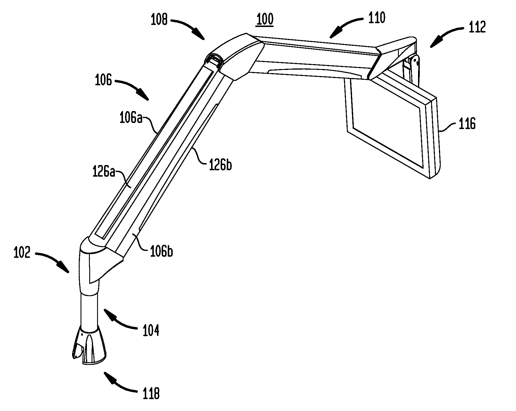
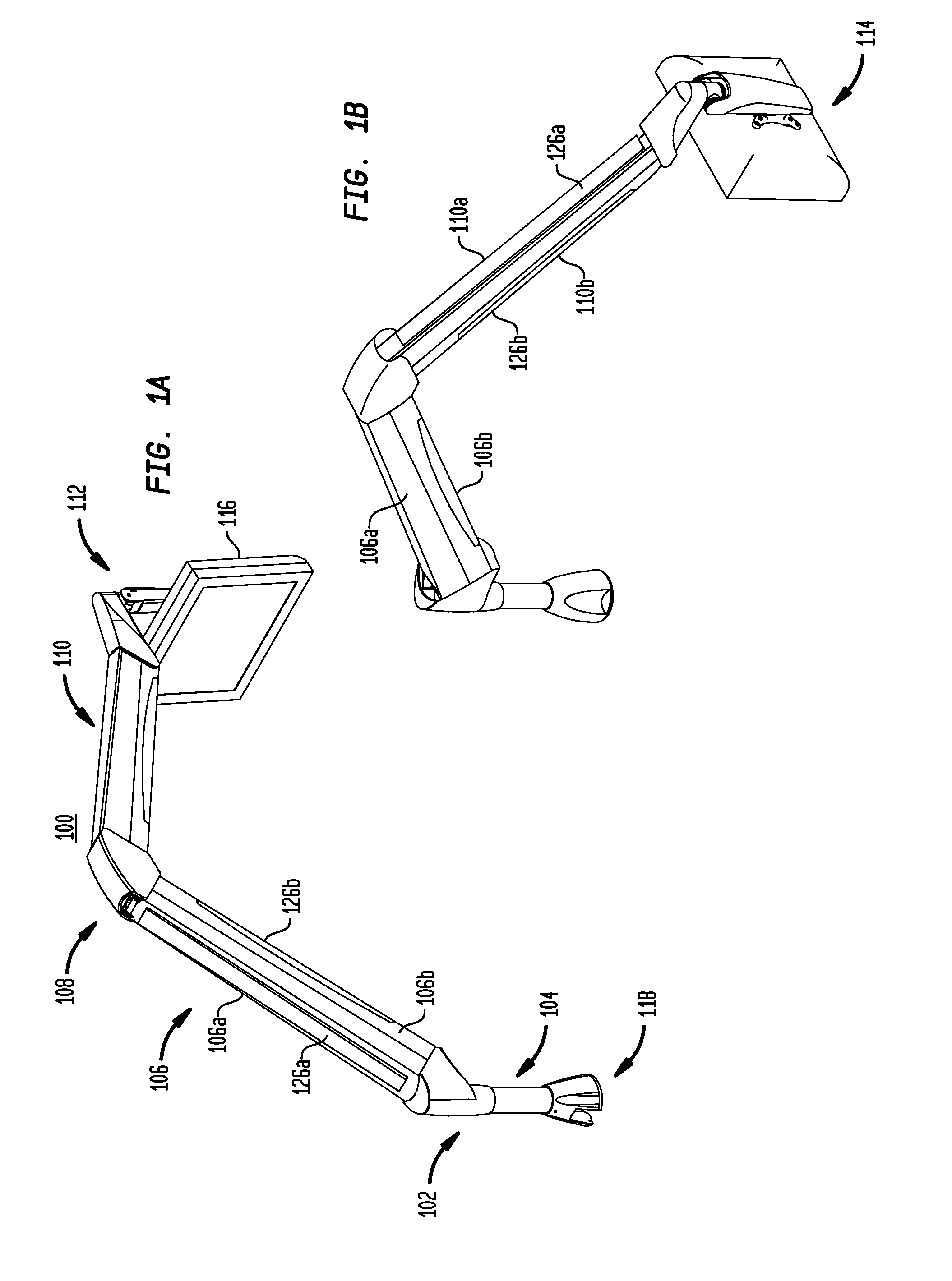
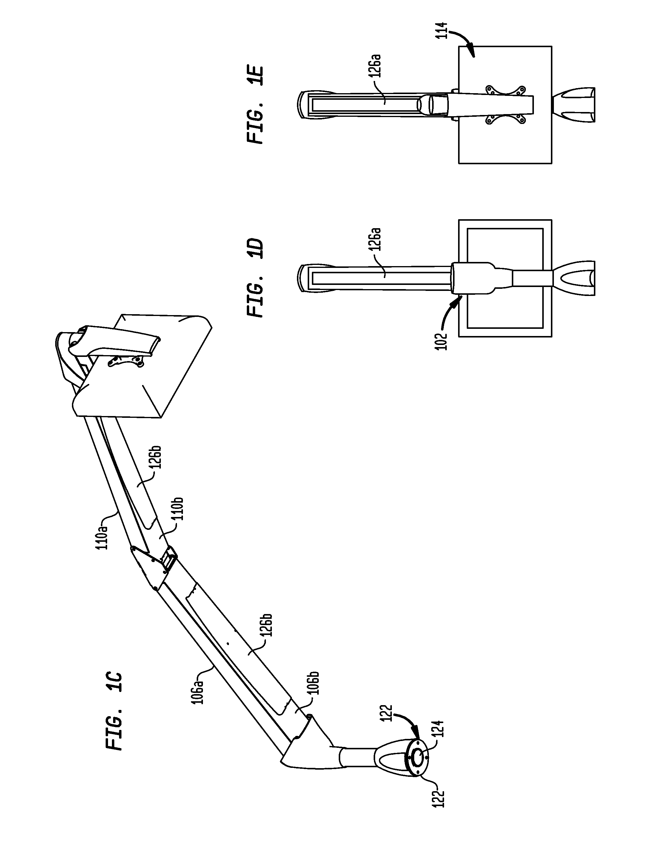
[0060]FIGS. 1A-H illustrate a preferred embodiment of an adjustable support apparatus such as extension arm assembly 100 in accordance with aspects of the present invention. As shown, the assembly 100 includes a first endcap 102 that connects at one end to a base member 104 and at the other end to a first arm member 106. The base member 104 may be separate from the first endcap 102 or may be part of the first endcap 102. The first arm member 106 is preferably connected to a middle cap 108 at a first side thereof. A second arm member 110 preferably connects to t...


PUM


Abstract

The present invention pertains to extension arm apparatuses that are adapted to support user devices throughout a range of positions. A given apparatus may include one or more arms that position the user device remotely from a support position. An extension and retraction device such as a gas cylinder is received within each arm, and provides a force to support the user device as the arm is placed into a given position. A variable force clevis is connected to the extension / retraction device within the arm. The variable force clevis is connected to a pair of locations in the arm as well. As the arm moves, for instance up or down, the variable force clevis rotates within the arm and dynamically adjusts the force provided by the extension / retraction device. Removable and / or pivotable covers are provided for managing cables of the user device attached to the extension arm.

Description

CROSS-REFERENCE TO RELATED APPLICATIONS[0001]The present application is a continuation-in-part of U.S. patent application Ser. No. 11 / 544,076, entitled “Extension Arm with Moving Clevis, filed Oct. 6, 2006, is a continuation-in-part of U.S. Design patent application Ser. No. 29 / 266,148, entitled “Boom Extension Arm,” filed Sep. 15, 2006, and is a continuation-in-part of U.S. Design patent application Ser. No. 29 / 267,176, entitled “Boom Extension Arm,” filed Oct. 6, 2006, the entire disclosures of which are hereby expressly incorporated by reference herein. The present application is related to U.S. Design patent application Ser. No. 29 / 288,254, entitled “Boom Extension Arm with Cable Management,” filed concurrently herewith, the entire disclosure of which is hereby expressly incorporated by reference herein.BACKGROUND OF THE INVENTION[0002]The present invention relates to adjustable extension arm apparatuses for use with electronic devices. More particularly, the present invention r...

Claims


Application Information

Patent Timeline
Patent Type & Authority Patents(United States)
IPC IPC(8): E04G3/00
CPCF16M11/04F16M11/06F16M11/105F16M11/2064F16M11/2092F16M13/02F16M11/24Y10T403/32139F16M2200/044F16M2200/063F16M2200/065
Inventor ALTONJI, ROBERTBOWMAN, STEVEVANDUZER, DAVIDDERRY, BRADLEY A.WILLIAMS, JR., HOWARD M.
Owner INNOVATIVE OFFICE PROD LLC
Why Eureka
Try Eureka