High pressure resonant vibrating-tube densitometer

a vibrating-tube densitometer and high-pressure technology, which is applied in the field of high-pressure vibrating-tube densitometers, can solve the problems of escalating recent problems and the difficulty of interstate and international transportation of nuclear densitometers

Active Publication Date: 2009-06-23
HALLIBURTON ENERGY SERVICES INC
View PDF24 Cites 52 Cited by
  • Summary
  • Abstract
  • Description
  • Claims
  • Application Information

AI Technical Summary

Problems solved by technology

However, although these radioactive sensors provide an accurate and compact means of measuring fluid density, there are many problems associated with the use of these nuclear densitometers, and in this time of increasing security, these problems have been escalating recently.
One problem associated with nuclear densitometers is that interstate and international transport of nuclear densitometers can be a difficult process due to the numerous and severe laws and regulations regarding nuclear technology.
These health and safety issues, shipping difficulties, and record-keeping burdens motivate development of non-radioactive alternatives for fluid density determination.

Method used


Image

  • High pressure resonant vibrating-tube densitometer
  • High pressure resonant vibrating-tube densitometer
  • High pressure resonant vibrating-tube densitometer

Examples


first embodiment

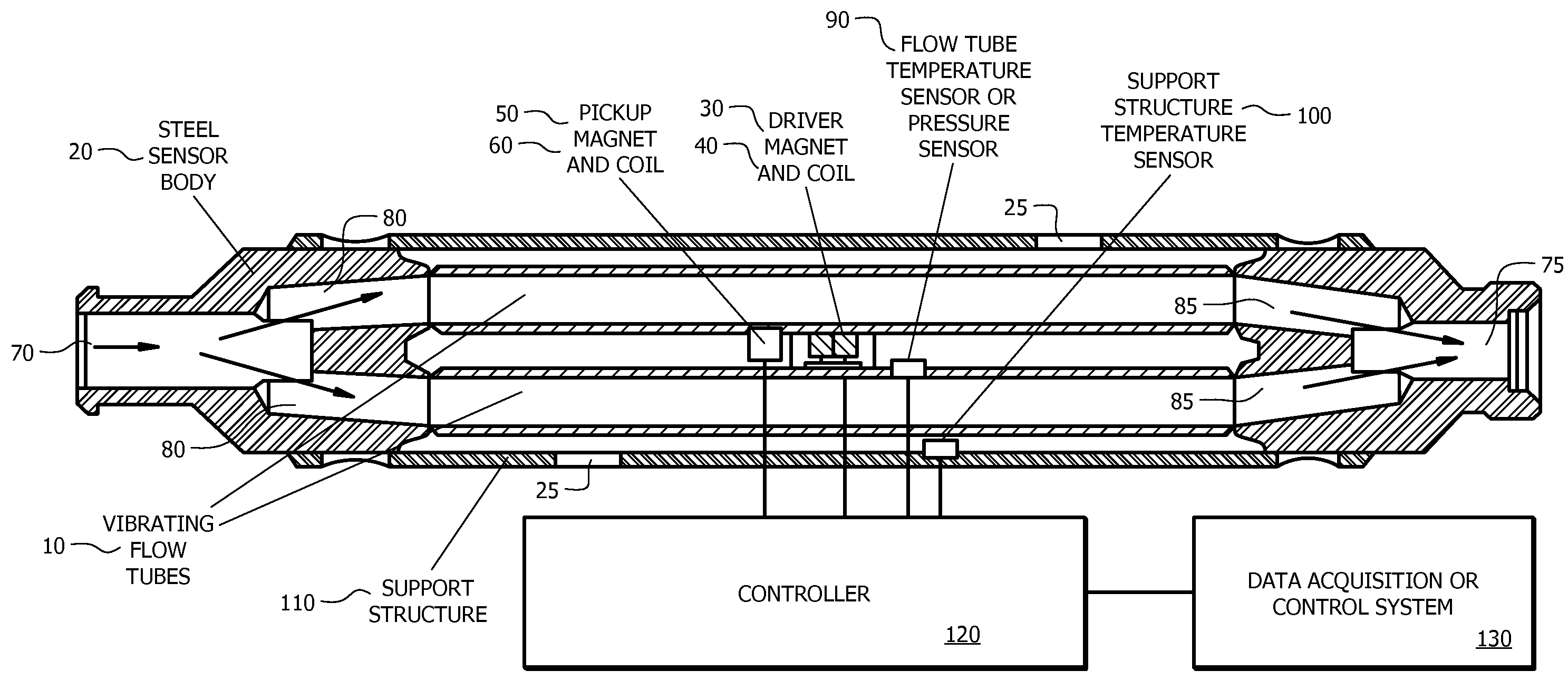
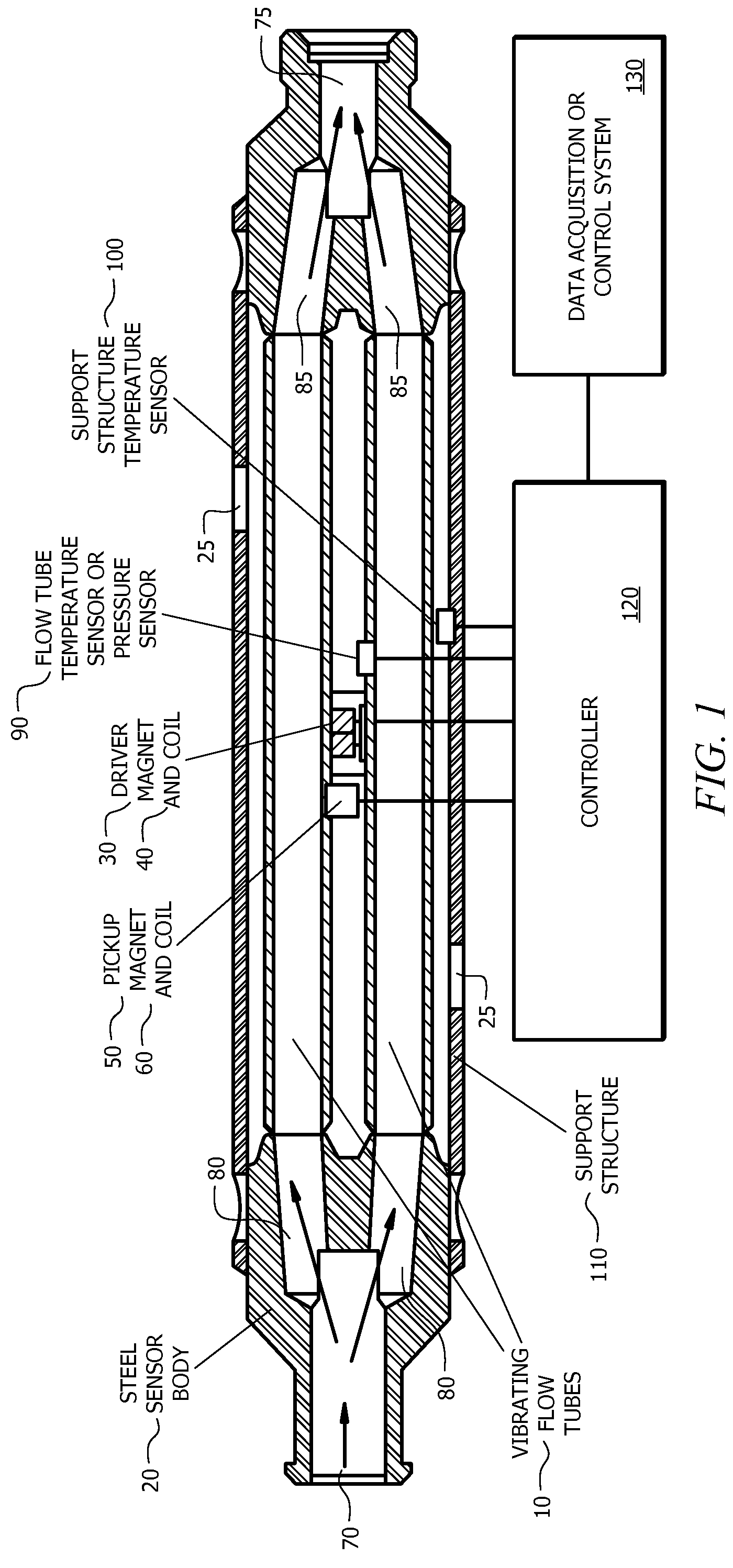
[0017]FIG. 1 is a depiction of an apparatus of the present disclosure.

second embodiment

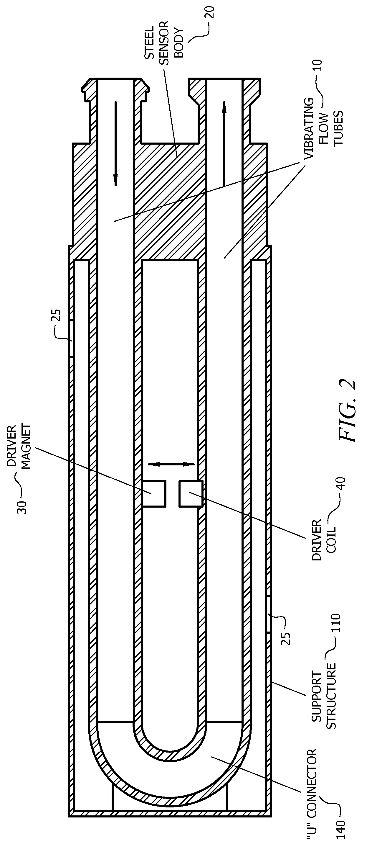
[0018]FIG. 2 is a depiction of an apparatus of the present disclosure.

third embodiment

[0019]FIG. 3 is a depiction of an apparatus of the present disclosure.

DETAILED DESCRIPTION OF THE PREFERRED EMBODIMENTS

[0020]Disclosed herein are various embodiments of a high pressure vibrating tube densitometer, hereinafter HPVT densitometer. The HPVT densitometer comprises parallel straight vibrating flow tubes as well as a driving means for initiating vibration of the fluid-filled flow tubes and a pickup means for sensing these vibrations from which fluid density is determined. The term “vibrating” flow tubes is used herein for ease of reference, however, it should be understood that, oftentimes, the tubes are only actually “vibrating” during use of the densitometer.

[0021]Also disclosed herein are methods for the manufacture of the HPVT densitometer. In some embodiments, these methods of manufacture comprise a welded construction and the formation of a pre-sensor assembly (hereinafter PSA) comprising the main non-temperature-sensitive components of the HPVT densitometer and port...


PUM

PropertyMeasurementUnit
pressureaaaaaaaaaa
pressuresaaaaaaaaaa
temperatureaaaaaaaaaa

Abstract

A method of manufacturing a high pressure vibrating tube densitometer comprising enclosing twin flow tubes within an outer shell, wherein the outer shell comprises portals for the installation or replacement of internal components. A vibrating tube densitometer system for determining the density of a high pressure fluid in a pipeline, the system comprising a densitometer in communication with a controller, the densitometer comprising twin straight flow tubes spaced parallel apart within an outer shell comprising one or more portals for the placement of internal components, wherein the controller is in signal communication with a signal pickup, a tube driver, and the at least one temperature or pressure sensor and calculating the density of a fluid having a pressure of greater than 1500 psi.

Description

CROSS-REFERENCE TO RELATED APPLICATIONS[0001]Not applicable.STATEMENT REGARDING FEDERALLY SPONSORED RESEARCH OR DEVELOPMENT[0002]Not applicable.BACKGROUND OF THE INVENTION[0003]1. Field of the Invention[0004]The present disclosure relates to an apparatus and method for making the apparatus used to determine the density of a high pressure fluid. More particularly, the present disclosure is directed to a high pressure vibrating-tube densitometer and a method for making a high pressure vibrating tube densitometer, the densitometer operable at fluid pressures greater than 1500 psi.[0005]2. Background of the Invention[0006]A natural resource such as oil or gas residing in a subterranean formation can be recovered by drilling a well into the formation. The subterranean formation is usually isolated from other formations using a technique known as well cementing. In particular, a wellbore is typically drilled down to the subterranean formation while circulating a drilling fluid through the...

Claims


Application Information

Patent Timeline
Patent Type & Authority Patents(United States)
IPC IPC(8): G01N9/02G01F1/84
CPCE21B47/10G01N9/002
Inventor HEADRICK, DICK C.
Owner HALLIBURTON ENERGY SERVICES INC
Why Eureka
Try Eureka