Method of forming hydroformed member with opening

a hydroformed member and opening technology, applied in the field of manufacturing a hydroformed member with an opening, can solve the problems of increasing manufacturing costs, time-consuming and expensive, and cutting the laser is time-consuming and laborious

Active Publication Date: 2009-06-30
MAGNA INTERNATIONAL INC
View PDF13 Cites 6 Cited by
  • Summary
  • Abstract
  • Description
  • Claims
  • Application Information

AI Technical Summary

Problems solved by technology

Laser cutting is, however, time consuming and expensive, both of which increase manufacturing costs.

Method used


Image

  • Method of forming hydroformed member with opening
  • Method of forming hydroformed member with opening
  • Method of forming hydroformed member with opening

Examples


Embodiment Construction

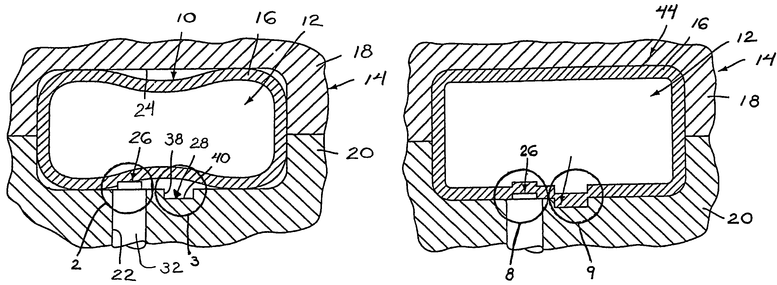
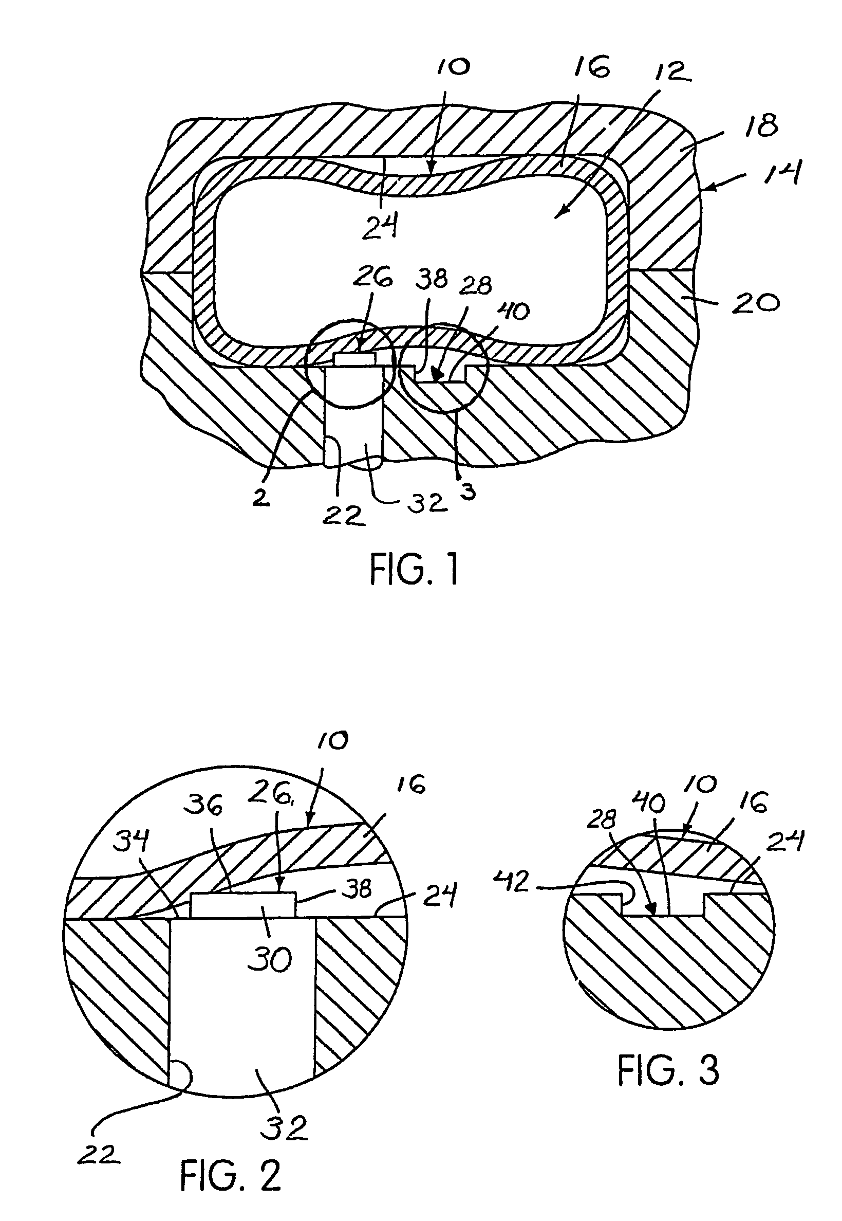
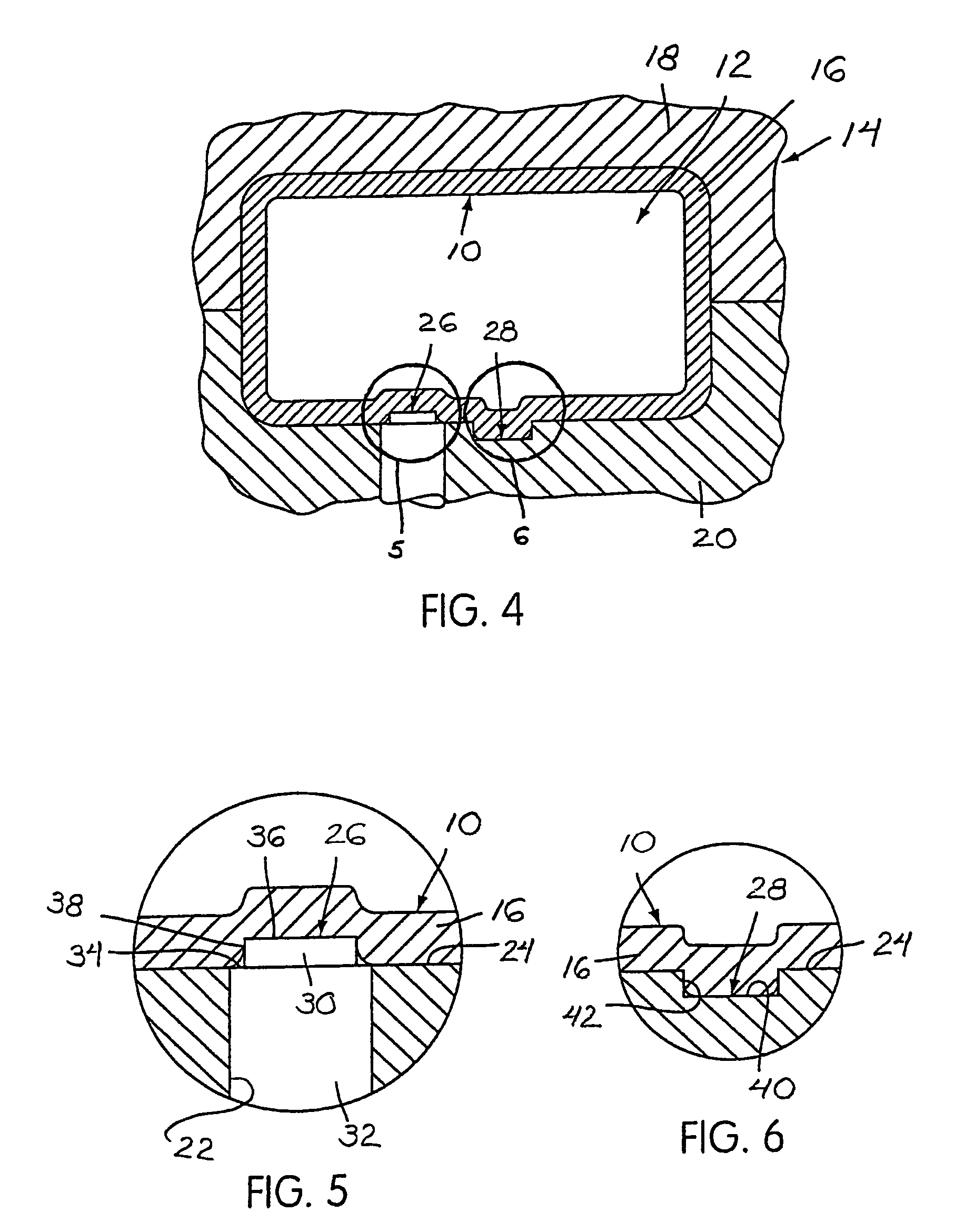
[0022]Referring to FIGS. 1 through 3, a tubular blank, generally indicated at 10, is disposed within a die cavity 12 of a die assembly, generally indicated at 14. The blank 10 is formed from a metal material, and includes a blank wall 16.

[0023]The die assembly 14 includes upper 18 and lower 20 die halves. The upper 18 and lower 20 die halves define the die cavity 12. In addition, the upper 18 and lower 20 die halves move towards and away from each other to selectively allow access to the die cavity 12. The lower die half 20 includes a die opening 22 that opens into the die cavity 12. It should, however, be appreciated that the die opening 22 may be formed in the upper die half 18.

[0024]A die surface 24 extends along the upper 18 and lower 20 die halves of the die assembly 14, and further defines the die cavity 12. The die surface 24 includes a pair of wall thinning elements 26, 28. One of the wall thinning elements 26, 28 is a projecting structure 26. The projecting structure 26 inc...


PUM

PropertyMeasurementUnit
thicknessaaaaaaaaaa
forceaaaaaaaaaa
pressureaaaaaaaaaa

Abstract

A method for manufacturing a hydroforming member includes the step of providing a blank (10). The blank (10) is defined by blank wall (16). The blank (10) is placed in a die assembly (14) having a die cavity (12) defined by a die surface (24). The blank (10) is expanded so that the blank wall (16) is forced against the die surface (24) to form the hydroformed member. A portion of the blank wall conforms against a wall-thinning element (26, 28) positioned along the die surface (24) to form a removable wall section (46, 50) in a portion of the blank wall (24). The removable wall section (46, 50) is then removed from the blank wall (16) to form an opening in the hydroformed member.

Description

CROSS REFERENCE TO RELATED APPLICATION[0001]This application claims the benefit of and priority from U.S. Provisional Patent Application Ser. No. 60 / 425,254, filed Nov. 12, 2002.BACKGROUND OF THE INVENTION[0002]1. Field of the Invention[0003]This invention relates to a method of manufacturing a hydroformed member. More particularly, the invention relates to a method of manufacturing a hydroformed member with an opening.[0004]2. Description of Related Art[0005]Hydroforming is a process in which high pressure fluid is utilized to move a blank into conformity with a die surface of a die assembly. In one example, a tubular blank may be expanded to conform with the die surface to form a tubular hydroformed member. It may sometimes be required to form a tubular member with one or more openings. These openings may be made during the manufacture of the hydroformed member. For example, laser cutting may be used to form at least one removable wall section along the tubular member. The removab...

Claims


Application Information

Patent Timeline
Patent Type & Authority Patents(United States)
IPC IPC(8): B21D47/00B21D26/02B21D47/02B21D51/00B21D26/025B21D26/035B21D28/28
CPCB21D26/025B21D26/035B21D28/28Y10T29/49622Y10T29/49805Y10T29/49616
Inventor DICESARE, JOHN
Owner MAGNA INTERNATIONAL INC
Why Eureka
Try Eureka