Vehicle connector lockout apparatus and method of using same

Active Publication Date: 2009-06-30
AIRMIKA INC
View PDF12 Cites 902 Cited by
  • Summary
  • Abstract
  • Description
  • Claims
  • Application Information

AI Technical Summary

Benefits of technology

[0039]The main objective of the present invention is to keep unauthorized peripheral devices from being connected to a vehicle onboard diagnostic link connector universal serial bus port without the consent or knowledge of vehicle owners (or operators) by providing means to deny physical access to the port, by attaching a connector lockout apparatus onto the diagnostic link connector port. This objective does not reduce, obstruct or hamper legitimate usage of the diagnostic link port for vehicle inspection, analysis of vehicle emissions, maintenance, or repair of the vehicle since these tasks are generally performed with the knowledge and consent of the owner or operator. The invention is specifically concerned with securing vehicle crash data, preventing mischief and misuse and thereby increasing consumer knowledge and acceptance of event data recorder technologies.
[0043]This preferred mechanism for implementing the invention has the advantage of simplicity and ease of construction with existing key-lock mechanisms. The preferred mode of the invention may also be implemented with other mechanisms for applying a clamping pressure to the protrusion. For example, an electro-mechanical mechanism could be used, and such a mechanism could be operated remotely using a coded radio signal. Other variations of this new and novel locking clamp methodology may also be used, based on variations in protrusion shape and size, to secure the diagnostic link connector without disturbing the electrical function of the vehicle sub-system.

Problems solved by technology

However, automakers may choose to modify future pin spacing that would negate this locking method.

Method used


Image

  • Vehicle connector lockout apparatus and method of using same
  • Vehicle connector lockout apparatus and method of using same
  • Vehicle connector lockout apparatus and method of using same

Examples


Embodiment Construction

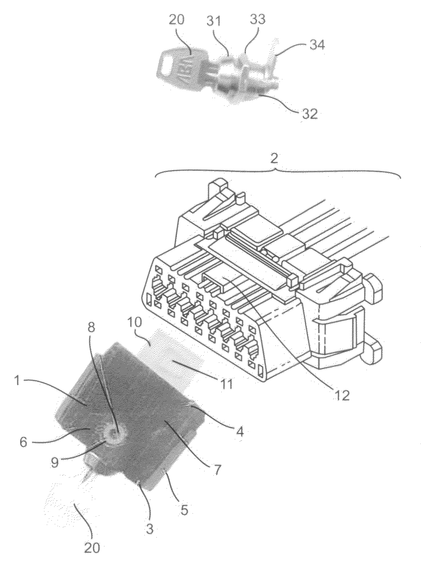
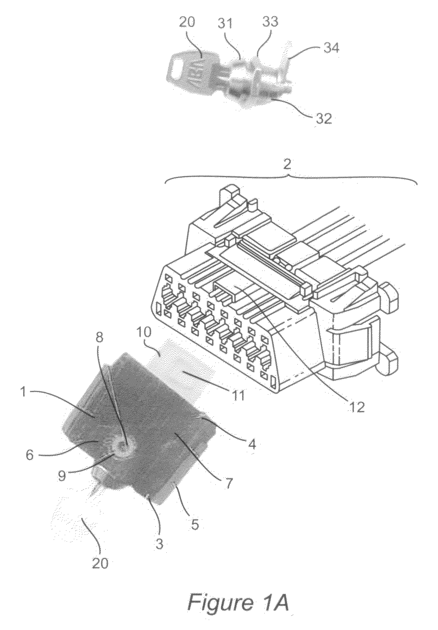
[0058]The present invention will now be described with reference to the attached drawings. The present invention hampers and prevents access to and thus misuse of motor vehicle information systems and crash data by providing a means to restrict physical access to the vehicle diagnostic link connector port, which is located under the vehicle dashboard as illustrated in FIGS. 1B and 1C. Turning to FIG. 1A, there is shown an overview of the lockout device 1 (shown as item 102 in FIG. 1) as connected to a vehicle diagnostic port 2. The device has a front wall 3, a rear wall 4, two side walls (e.g. 5) and a top wall 6 and bottom wall 7. There is an open security slot 8 and a cylindrical or button assembly 9. A locking plate 10 contains a hole 11. The device 1 is made operable by mating to a diagnostic connector 2 having a protrusion 12, and turning key 20 to clamp the locking plate 10 to the protrusion 12. Key 20 is inserted into keyed opening 31, and turning the key 20 rotates cylinder ...


PUM


Abstract

According to the present invention, a vehicle connector lockout apparatus capable of being connected to the diagnostic port of a vehicle is provided. The preferred embodiment of the invention uses a raised protrusion, located in the common space below the two rows of pin spacing of the diagnostic port, as a locking point. The preferred embodiment provides a blocking mating connector with a pressure mechanism for clamping the mating connector to the protrusion. In the preferred embodiment the pressure mechanism is activated and released mechanically by operation of a key in a key lock which is an integral part of the mating connector, where rotation of the key to the locked position in the key lock applies pressure to the protrusion so as to clamp the blocking mating connector to the protrusion. A further embodiment of the invention provides a non-volatile microchip memory component to store information about the vehicle operator usable by medical personnel at the scene of a crash.

Description

[0001]This application is a continuation in part from U.S. patent application Ser. No. 11 / 618,550 of the same title, which is incorporated herein by reference, and which was filed on Dec. 29, 2006 now abandoned claiming priority from now-expired U.S. Provisional Patent Application 60 / 754,899 of the same title filed on Dec. 30, 2005.BACKGROUND OF THE INVENTION[0002]1. Field of the Invention[0003]The present invention relates to motor vehicle connector lockout devices, and in particular to lockout devices for vehicle diagnostic data link connectors.[0004]2. Background Description[0005]The past four decades have witnessed an exponential increase in the number and sophistication of electronic systems in vehicles. A vast increase in automotive electronic systems, coupled with related memory storage technologies, has created an array of new safety engineering opportunities and subsequent consumer acceptance challenges.[0006]Virtually every passenger car and light truck manufactured in or ...

Claims


Application Information

Patent Timeline
Patent Type & Authority Patents(United States)
IPC IPC(8): H01R13/44
CPCH01R13/443H01R13/6397
Inventor KOWALICK, THOMAS M.
Owner AIRMIKA INC
Why Eureka
Try Eureka