Tracking solar collector assembly

a solar collector and assembly technology, applied in the field of solar energy collection, can solve the problems of difficult or impossible to move more than one row of solar panels with a single driver

Active Publication Date: 2009-06-30
SUNPOWER CORPORATION
View PDF49 Cites 74 Cited by
  • Summary
  • Abstract
  • Description
  • Claims
  • Application Information

AI Technical Summary

Benefits of technology

[0008]One aspect of the invention is directed to tracking solar collector assembly including first and second Southside supports and first, second and third north side supports. The Southside supports and the North side supports define first and second generally parallel paths. The assembly also includes first and second solar collector support structures. Each solar collector support structure has first and second spaced apart pivotal support points, the support points defining a tilt axis. At least one solar collector is mounted to each solar collector support structure. The first support points of the first and second solar collector support structures are pivotally connected to and supported by the first and second Southside supports, respectively. The second support point of the first solar collector support structure is pivotally connected to and supported by the first and second North side supports. The second support point of the second solar collector support structure is pivotally connected to and supported by the second and third North side supports. The assembly further includes a tilting assembly. The tilting assembly includes a drive element secured to eac

Problems solved by technology

With a pier-mounted drive, it is difficult or impossible to u

Method used


Image

  • Tracking solar collector assembly
  • Tracking solar collector assembly
  • Tracking solar collector assembly

Examples


Embodiment Construction

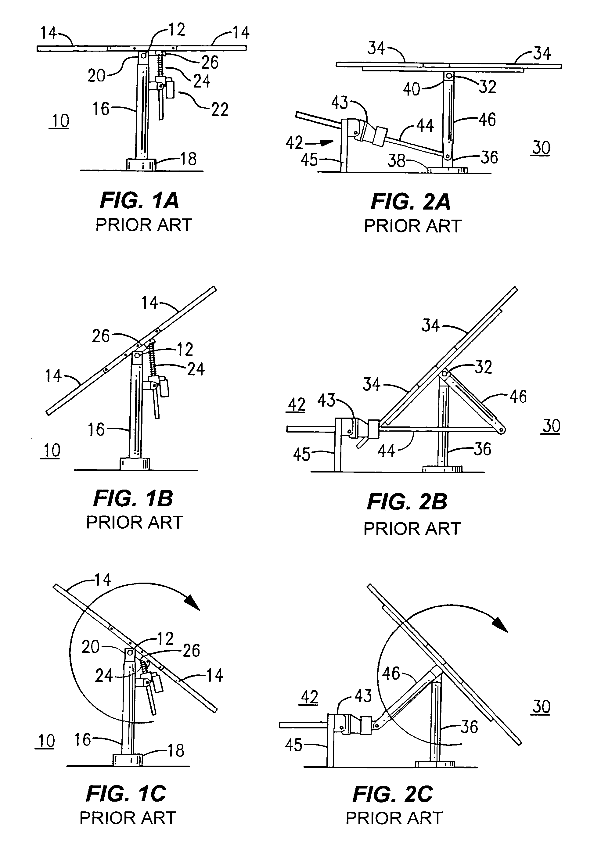
[0041]With reference to the Drawing, and initially to FIGS. 1A to 1C, a solar tracker array 10 according to the prior art, here is shown from a north aspect. A torque tube 12 serves as a north-south axis, and a row of solar panels 14 is attached onto the tube 12. These are balanced with panels similarly situated on both the east and west sides of the axis. However, as used here the term “balanced” is not strictly limited to having the panels arranged in identical fashion on each side of the tube 12. Some imbalance can be permitted, depending on mechanical factors. A vertical pier 16 has a footing 18, e.g., formed of poured concrete, serving as a foundation that is supported in the earth. There is a pivot eye 20 at the top of the pier to support the torque tube 12 so that the row of solar panels 14 can be rocked from an east-facing orientation (FIG. 1B) throughout the day to a mid-day, generally flat orientation (FIG. 1A) and to a west-facing orientation (FIG. 1C). In order to effect...


PUM


Abstract

A tracking solar collector assembly includes Southside supports, North side supports and support structures. Each support structure has pivotal support points defining a tilt axis and supports at least one solar collector. First support points of first and second support structures are pivotally connected to first and second Southside supports. A second support point of the first support structure is pivotally connected to first and second North side supports. A second support point of the second support structure is pivotally connected to second and third North side supports. A tilting assembly causes the solar collector support structures and the solar collectors tilt in unison. A tracking solar collector may comprise a torsion tube rotatable about a torsion tube axis; with the solar panels secured to the torsion tube at an angle with the solar panels located entirely above the torsion tube at noontime.

Description

CROSS-REFERENCE TO OTHER APPLICATIONS[0001]This application claims the benefit of U.S. Provisional Application No. 60 / 455,649, filed Mar. 18, 2003 and U.S. Provisional Patent Application No. 60 / 530,384, filed 17 Dec.[0002]2003. This application is related to U.S. Pat. No. 6,058,930, issued 9 May 2000.FEDERALLY SPONSORED RESEARCH OR DEVELOPMENT[0003]None.BACKGROUND OF THE INVENTION[0004]This invention relates to solar energy collection, and in particular to an arrangement for driving a number of rows of solar panels to track the motion of the sun relative to the earth. The invention is more particularly directed to improvements in efficiency and reliability in the tracker arrangement for rocking, or rotating, a group or array of rows of solar panels. The invention applies to solar collectors in which the panels are arrays of photovoltaic cells for generating electrical power, but the same principles can be applied also to arrangements for solar heating, for example.[0005]Photovoltaic...

Claims


Application Information

Patent Timeline
IPC IPC(8): E04B7/02H01L25/00H02N6/00F24J2/54F24S50/20
CPCF24J2/38F24J2/54F24J2/541H01L31/042F24J2/523F24J2002/0084Y02E10/50F24J2002/5468Y02B10/20Y02E10/47F24J2002/5451H02S20/32H02S20/10F24S2020/16F24S50/20F24S30/425F24S25/10F24S2030/131F24S30/40F24S2030/136
Inventor SHINGLETON, JEFFERSON G.
Owner SUNPOWER CORPORATION
Why Eureka
Try Eureka