
Fold flat seating

a flat seating and seat technology, applied in the field of vehicle folding seats, can solve the problems of cargo vehicles having second, third or other multiple row seating units, cargo vehicles that have multiple row seats, and are too long for the truck bed,

Inactive Publication Date: 2009-07-14
SCHUKRA OF NORTH AMERICA
View PDF17 Cites 30 Cited by
  • Summary
  • Abstract
  • Description
  • Claims
  • Application Information

AI Technical Summary

Problems solved by technology

Frequently the cargo to be hauled is too long for the bed of the truck.
In this case, for example if hauling a standard sized sheet of plywood, the sheet must be laid down in the bed with the tailgate of the truck fully opened, or the sheet must be rested at the rearward end on top of the closed tailgate, causing the sheet to sag.
In the past, cargo vehicles having second, third, or other multiple row seating units proved to be very unpopular.
The seating units were difficult to manipulate and took away valuable space both inside the passenger compartment and within the vehicle chassis area because extra, unused seats would have to be stored in a deep, recessed well in the chassis.
Likewise, the seating units were not comfortable or aesthetically pleasing.
Users of such systems who wanted to maximize storage or cargo space would have to completely remove rear seats which created two associated problems.
First, the seats were bulky and heavy and difficult to maneuver in the confined space of vehicle occupancy compartments.
Additionally, seat removal created problems because the removed seat required storage in a garage, a home, or elsewhere, taking up valuable space.
Likewise, seating units that were not removed from the vehicle, but were instead folded and stored within a well in the vehicle chassis reduced ground clearance.
Ground clearance reduction in vehicles such as sport utility vehicles greatly limits the area drivers may operate the vehicles.
The known seat systems, however, often require awkward assemblies that use precious vehicle space or create storage problems.
Additionally, many folding seats are complicated and expensive to manufacture and assemble, comprising many gears and / or lever arms among other components.
Finally, many of the existing systems are not aesthetically pleasing or comfortable.
In particular, modifications to the seats to make them have a thinner profile when folded often lead to structural trade-offs which sacrifice comfort.
This forward placement of the seat base and the lower part of the seat back interferes with the use of the passenger compartment as cargo space, since the anchor point of the typical folding seat must stand away from the rear wall by a sufficient distance to achieve the optimum torso support angle when the seat is in the unfolded position.

Method used


Image

  • Fold flat seating
  • Fold flat seating
  • Fold flat seating

Examples


Embodiment Construction

[0077]The following description of the preferred embodiment(s) is merely exemplary in nature and is in no way intended to limit the invention, its application, or uses.

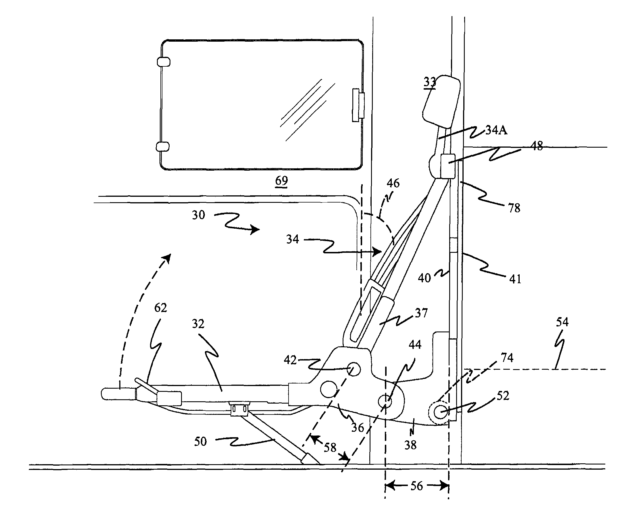
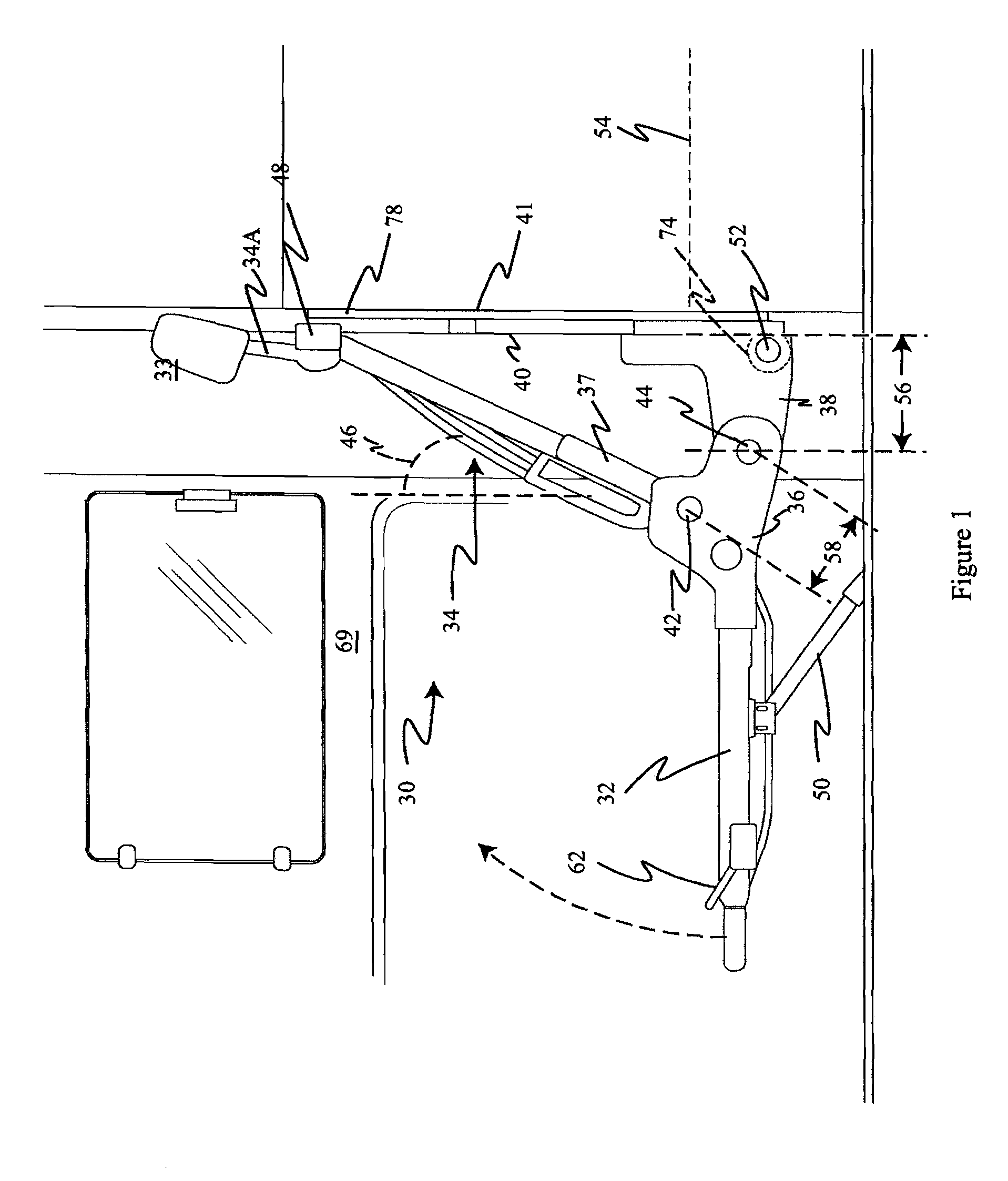
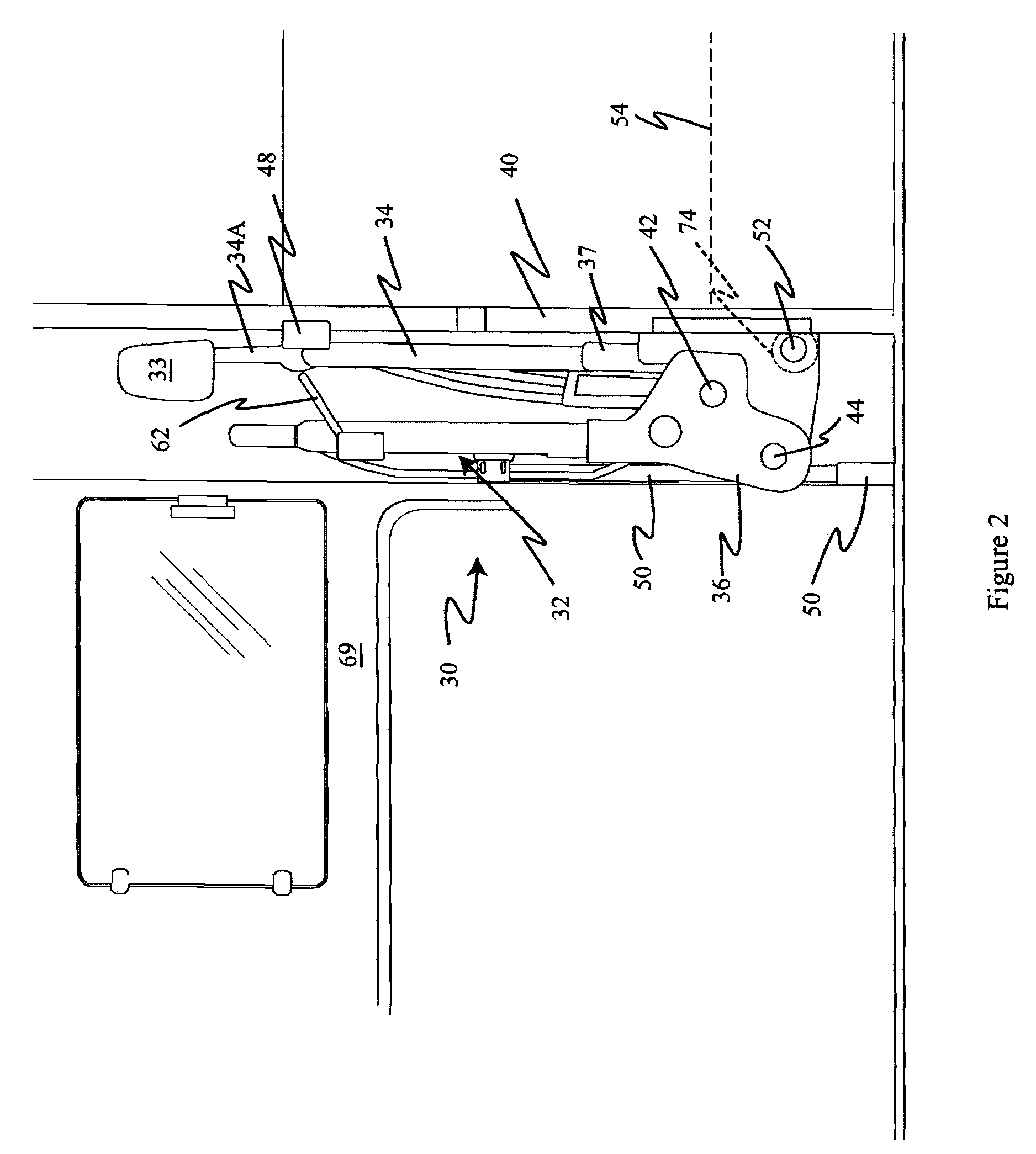
[0078]With reference to the figures, and initially FIG. 1, a stadium style fold down seat, generally designated 30 is constructed in accordance with the invention and includes a seat base 32, a seat back 34, a seat bracket 37 pivotally connected to an intermediate bracket 36, and a support bracket 38. It is to be understood throughout the following discussion that there may be multiple seats 30 disposed within the same vehicle V and, while ordinarily each seat 30 within a vehicle will be the same as the others, there may optionally be variations among them.

[0079]In the seat shown in FIGS. 1 and 2, seat base 32 is fixedly attached to seat bracket 37. Seat back 34 is hingedly (or “pivotally”) attached at a first hinge point 42 by seat bracket 37 to intermediate bracket 36. Seat back 34 is attached to intermediate 36 pre...


PUM


Abstract

A folding seat for a vehicle includes a seat base fixed to an intermediate bracket, a seat back having a lower end and a support bracket fixed to the vehicle. An intermediate bracket has a first hinge point where the seat back lower end is hingedly attached to the intermediate bracket. The intermediate bracket has a second hinge point where the intermediate bracket is hingedly attached to the support bracket, and which is spatially removed from the first hinge point. Upon folding of the seat base into a vertical position, the intermediate bracket rotates on the second hinge point, which remains stationary and the first hinge point rotates upwardly and rearwardly around the second hinge point, so that the first hinge point and the lower seat back move rearwardly as the seat back and the seat base are folded into vertical orientation close to the rear vehicle wall.

Description

CROSS-REFERENCE TO RELATED APPLICATIONS[0001]This application relies upon and claims the benefit of pending U.S. Ser. No. 60 / 778,955, filed Mar. 3, 2006, for a Stadium Style Folding Seat.BACKGROUND OF THE INVENTION[0002]1. Field of the Invention[0003]The present invention relates to folding seats for vehicles, particularly for use in the rear passenger compartment of extended cab trucks.[0004]2. Related Art[0005]By definition pick-up trucks are intended for hauling cargo of various sizes. Frequently the cargo to be hauled is too long for the bed of the truck. In this case, for example if hauling a standard sized sheet of plywood, the sheet must be laid down in the bed with the tailgate of the truck fully opened, or the sheet must be rested at the rearward end on top of the closed tailgate, causing the sheet to sag. Neither position of the cargo is preferred. Rather, it is best to be able to lay the entire sheet down, flat upon the bed of the truck and then close the tailgate to prev...

Claims


Application Information

Patent Timeline
Patent Type & Authority Patents(United States)
IPC IPC(8): B60N2/005B60N2/90
CPCB60N2/206B60N2/3013B60N2/3031B60N2/3047B60N2/305B60N2/3065B60R5/00B60N2/36B60N2/4606B60N2/4832B60N2/4855B60N2/4858B60N2/66B60N2/309B60N2/856B60N2/753B60N2/832B60N2/859
Inventor MCMILLEN, ROBERT J.
Owner SCHUKRA OF NORTH AMERICA
Learn More