
Eyeglass frame incorporating ornamented temple members

Inactive Publication Date: 2009-07-14
LLOYD STEVE
View PDF9 Cites 11 Cited by
  • Summary
  • Abstract
  • Description
  • Claims
  • Application Information

AI Technical Summary

Problems solved by technology

The device shown is substantially uniform along its length and therefore is incapable of conforming to the shape of the temple frame member.
However, a primary difficulty of this reference is the inability to interchange the orname

Method used


Image

  • Eyeglass frame incorporating ornamented temple members
  • Eyeglass frame incorporating ornamented temple members
  • Eyeglass frame incorporating ornamented temple members

Examples


Embodiment Construction

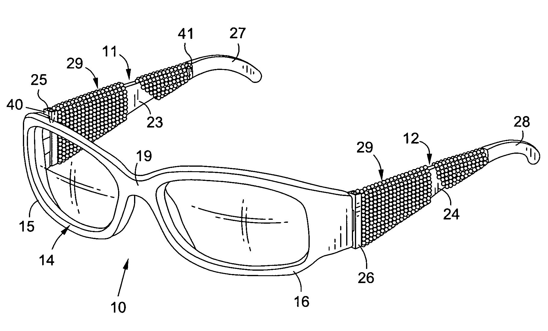
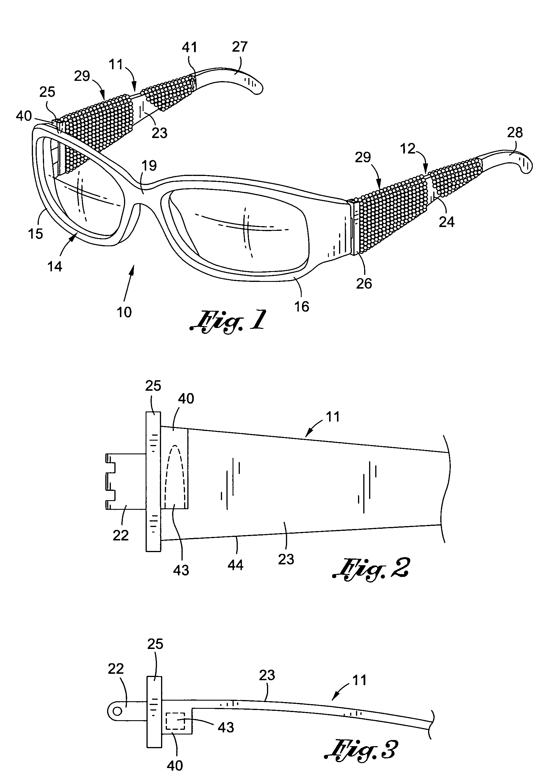
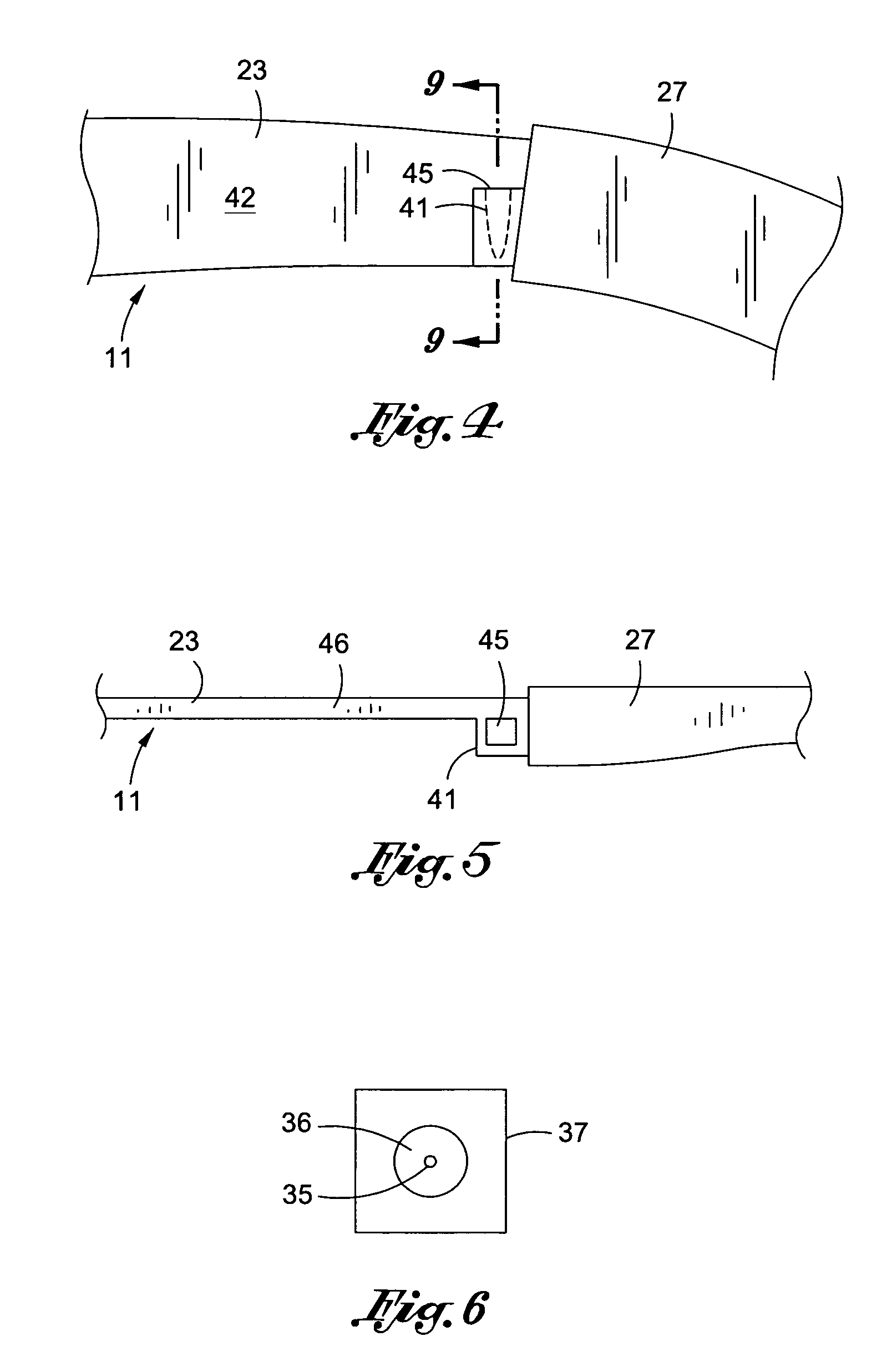
[0025]A general understanding of the present invention can be gained from FIGS. 1-5, inclusive, wherein an eyeglass assembly 10 and ornamented temple members 11 and 12 are shown. The eyeglass unit includes a front frame unit 14 having two lens holding elements 15 and 16 which hold lenses 17 and 18, respectively. It is understood that the lenses 17 and 18 may be prescription or non-prescription and may be darkened or clear. A nose bridge 19 connects the two lens-holding elements 15 and 16 together and serves to support the frame 13 on the face of the user. Two temple frame members 11 and 12 which are ornamented in accordance with the present invention are hingedly coupled to lens holding elements 15 and 16, respectively, by conventional hinges.

[0026]It is an objective of the present invention to provide eyeglass frames having ornamented temple frame members 20 and 21. The structure of temple frame members 11 and 12 can be best understood by reference to FIGS. 2-5, inclusive. Although...


PUM


Abstract

An eyeglass frame incorporates coupled temple frame members that are adapted to receive interchangeable ornamental trim members. Each trim member comprises an elongated, flexible ornamental assembly that is spirally mounted about each temple frame member between opposed predetermined locations along the longitudinal axis thereof. First and second trim positioners are secured to the ends of the trim member. The trim positioners are coupled to trim receivers that are secured to the temple frame members substantially adjacent the opposed predetermined locations thereof.

Description

BACKGROUND OF THE INVENTION[0001]1. Field of the Invention[0002]The invention generally relates to ornamented eye-glass frames and in particular to eyeglass frames incorporating temple frame members that are adapted to receive interchangeable ornamental trim members.[0003]2. Prior Art[0004]The prior art discloses numerous references that embody eyeglass frames having temple members and / or frame surfaces that are ornamented. An example of a reference that illustrates a device for ornamenting the temple frame members of eyeglasses is Applicant's patent No. D-341,609. The design disclosed is a tubular assembly of individual ornaments that can be removably disposed upon the temple frame member. The device shown is substantially uniform along its length and therefore is incapable of conforming to the shape of the temple frame member. The present invention design overcomes the inadequacy of the reference by using an ornamented trim member that is spirally mounted upon the central portion ...

Claims


Application Information

Patent Timeline
IPC IPC(8): G02C11/02
CPCG02C11/02
Inventor LLOYD, STEVE
Owner LLOYD STEVE
Learn More