Robotic floor cleaner

a robot and floor cleaner technology, applied in the direction of cleaning filter means, cleaning equipment, applications, etc., can solve the problem of not being able to operate manually to clean desired specific locations

Active Publication Date: 2009-08-04
HUNAN GRAND PRO ROBOT TECH
View PDF4 Cites 141 Cited by
  • Summary
  • Abstract
  • Description
  • Claims
  • Application Information

AI Technical Summary

Problems solved by technology

However, this design of robotic floor cleaner moves on the floor according to the designed steering mode, and is not operable manually for cleaning desired specific locations.

Method used


Image

  • Robotic floor cleaner
  • Robotic floor cleaner
  • Robotic floor cleaner

Examples


Embodiment Construction

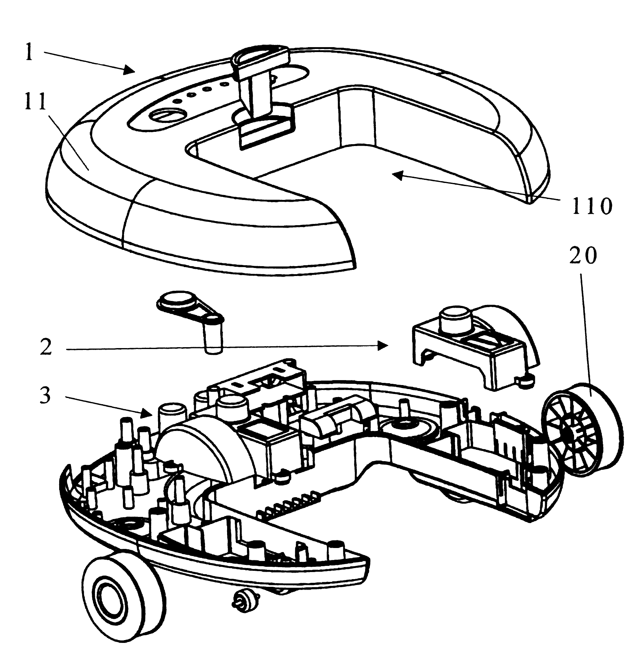
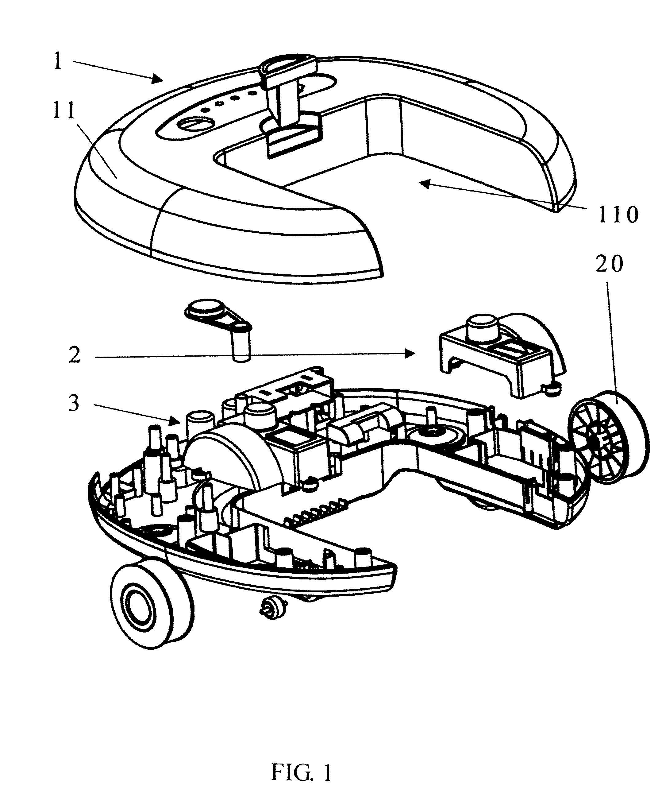
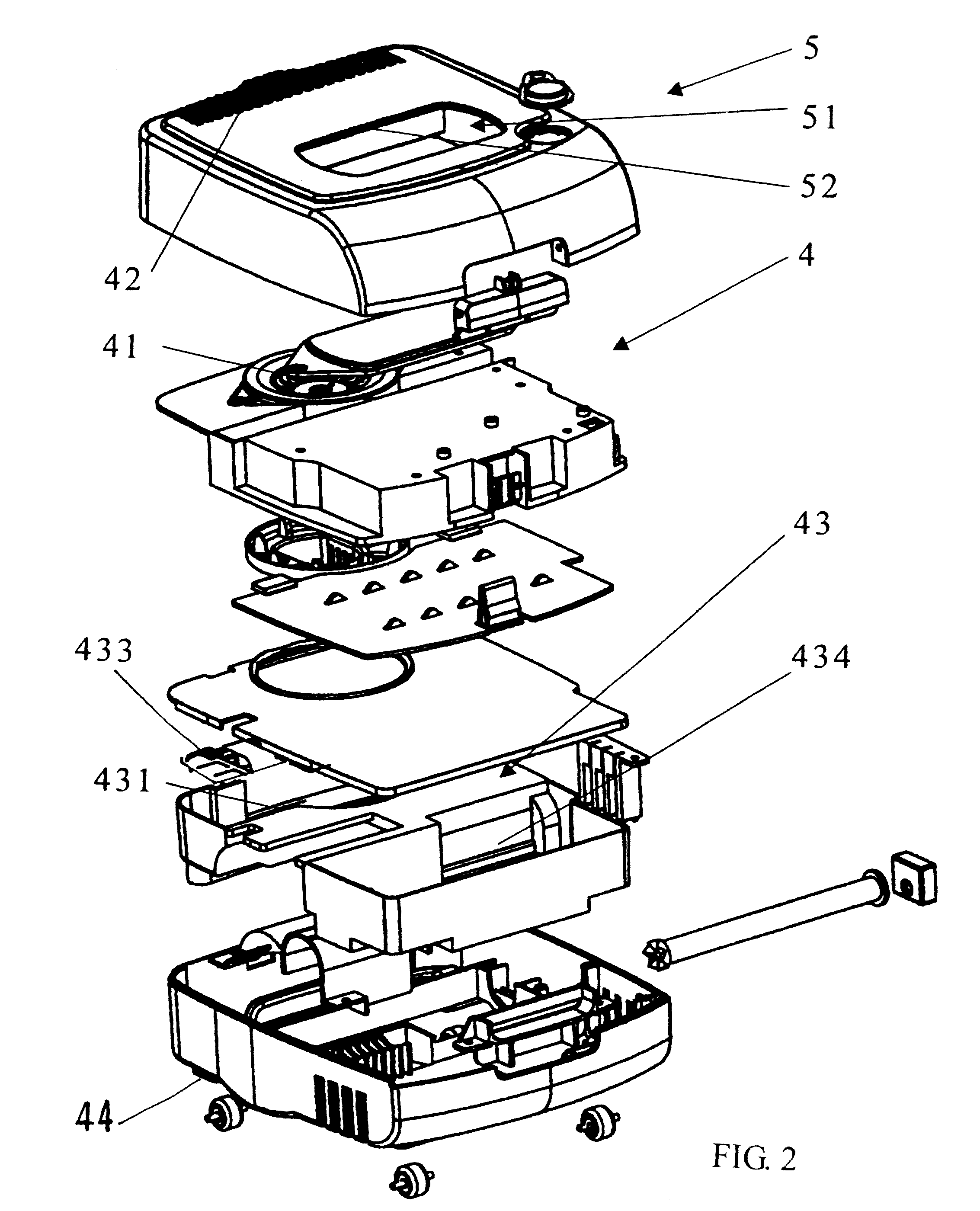
[0011]Referring to FIGS. 1 and 2, a robotic floor cleaner in accordance with the present invention is shown comprised of a main body 1, a daughter body 5, and a handle assembly 6. The main body 1 houses a propelling unit 2 and a control unit 3. The daughter body 5 houses a vacuum cleaner unit 4 for removing dust, waste paper chips, sands, hairs, etc. from the floor.

[0012]The main body 1 comprises a substantially U-shaped shell 11 defining an open space 110.

[0013]The propelling unit 2 comprises two steering wheels 20 symmetrically pivotally mounted in the main body 1 at two sides for moving the main body 1 on the floor. The control unit 3 is a circuit board fixedly mounted inside the main body 1 for controlling the operation of the propelling unit 2 to move the main body 1 on the floor according to a predetermined steering mode.

[0014]Referring to FIG. 2 again, the daughter body 5 is fastened to the main body 1 and suspended in the open space 11. The vacuum cleaner unit 4 is mounted i...


PUM


Abstract

A robotic floor cleaner includes a main body, which houses a propelling unit for moving the robotic floor cleaner on the floor and a control unit for controlling the operation of the propelling unit to move the robotic floor cleaner on the floor according to a predetermined steering mode, a daughter body detachably fastened to the main body and houses a vacuum cleaner unit for removing dust, and a handle assembly detachably connectable to the daughter body.

Description

BACKGROUND OF THE INVENTION[0001]1. Field of the Invention[0002]The present invention relates to floor cleaning apparatus and more particularly to a robotic floor cleaner, which can be alternatively set between a first status for automatic cleaning operation and a second status for manual cleaning operation.[0003]2. Description of the Related Art[0004]Following fast development of technology, various automatic home appliances have been disclosed and have appeared on the market. Taiwan patent publication number 92123812 discloses a robotic floor cleaner for cleaning the floor automatically. However, this design of robotic floor cleaner moves on the floor according to the designed steering mode, and is not operable manually for cleaning desired specific locations.SUMMARY OF THE INVENTION[0005]The present invention has been accomplished under the circumstances in view. It is an object of the present invention to provide a robotic floor cleaner, which can be alternatively set between a ...

Claims


Application Information

Patent Timeline
Patent Type & Authority Patents(United States)
IPC IPC(8): A47L5/00
CPCA47L5/225A47L5/28A47L2201/00
Inventor YAN, JASON
Owner HUNAN GRAND PRO ROBOT TECH
Why Eureka
Try Eureka