Door lock system

a door lock and lock body technology, applied in the direction of passenger lock actuation, carpet fasteners, lock applications, etc., can solve the problems of increased number of components, complicated structure, and interference between door-opening and unlocking operations

Active Publication Date: 2009-08-04
MITSUI KINZOKU ACT
View PDF14 Cites 23 Cited by
  • Summary
  • Abstract
  • Description
  • Claims
  • Application Information

AI Technical Summary

Problems solved by technology

When a door-opening operation is performed on a door lock system in a locked position using an outside handle of a vehicle while an unlocking operation is simultaneously performed using an inside lock knob of the vehicle, the door-opening and the unlocking operations interfere each other.
Accordingly, the number of components is increased and the structure is complicated, which poses a problem of an increase in the man-hours required for assembly and in the manufacturing cost.

Method used


Image

  • Door lock system
  • Door lock system
  • Door lock system

Examples


Embodiment Construction

[0037]Exemplary embodiments of the present invention are explained in detail below with reference to the accompanying drawings.

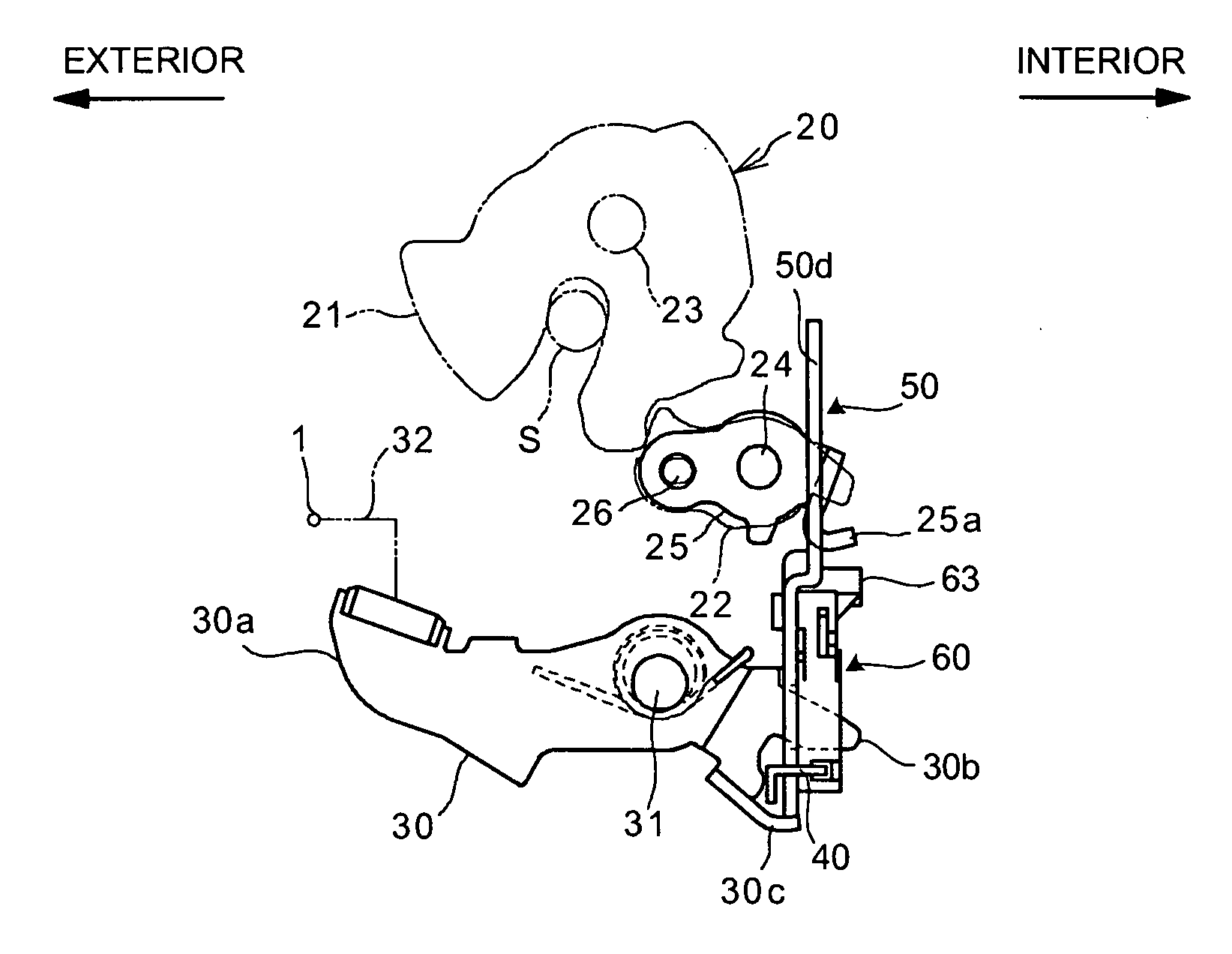
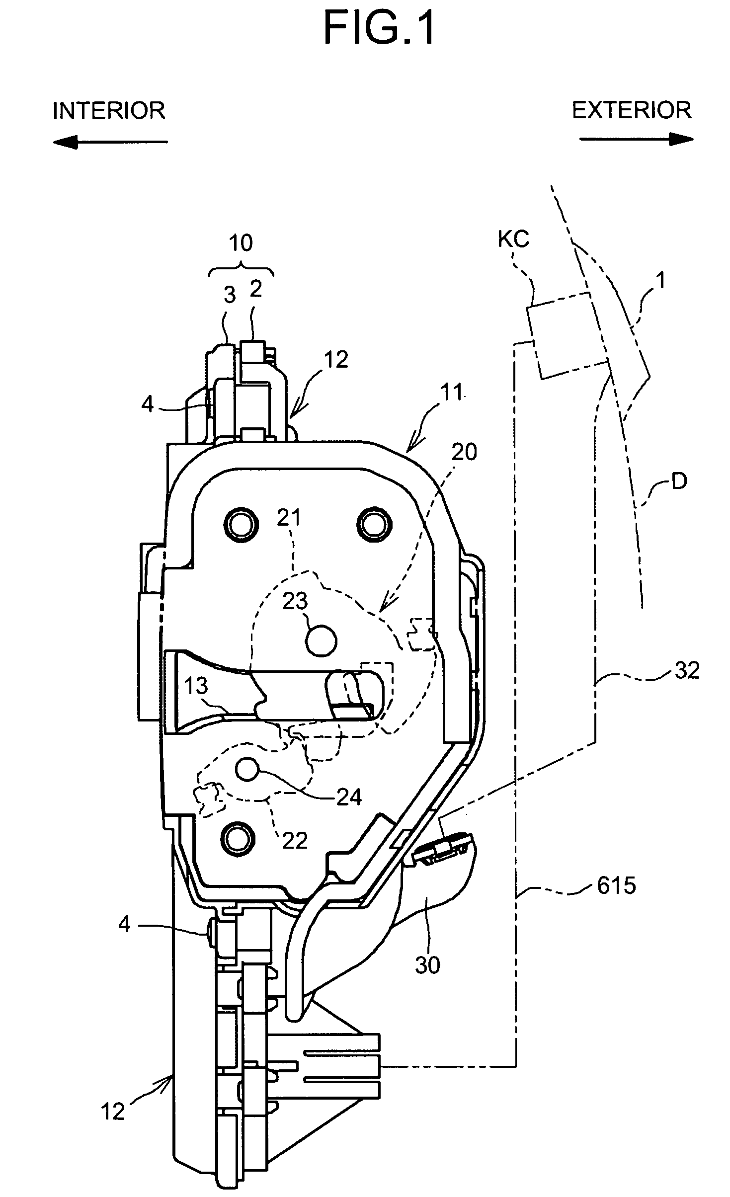
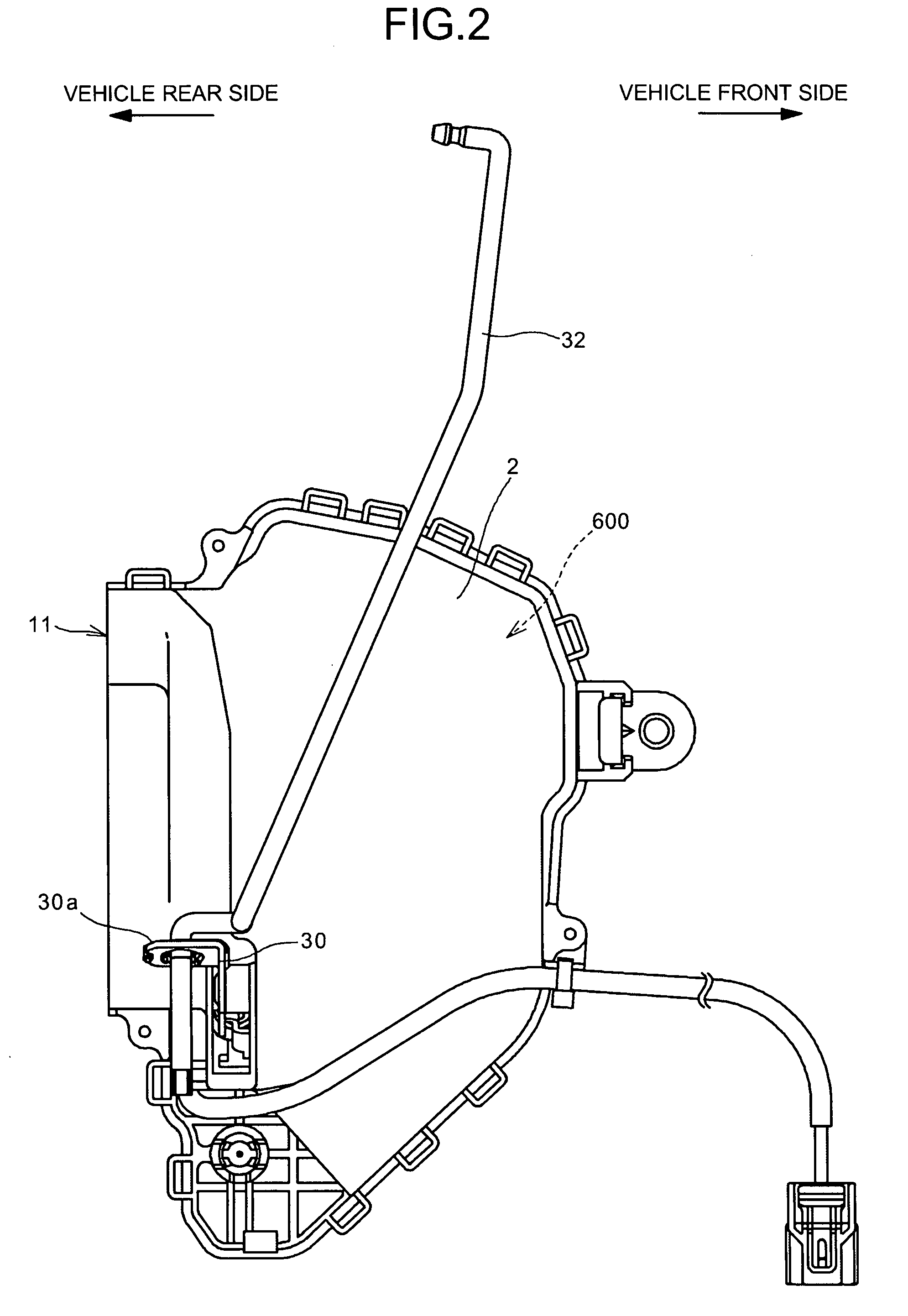
[0038]FIGS. 1 to 4 depict a door lock system according to an embodiment of the present invention. The door lock system is explained on the assumption that it is provided between an outside handle 1 and a latch mechanism 20 in a front-hinged side door on the right side of a front seat of a vehicle (a driver's door D of a right-hand drive vehicle). The door lock system includes a main casing 2 and a sub casing 3, each of which is formed from, e.g., a synthetic resin. The casings 2 and 3 are joined and fastened to each other by a fastening unit 4, such as a screw, to form a housing 10.

[0039]The housing 10 formed with the main casing 2 and sub casing 3 includes a latch-mechanism accommodating unit 11 and a lock-mechanism accommodating unit 12. The latch-mechanism accommodating unit 11 extends in a direction traversing the door D to and from the interior and the ...


PUM


Abstract

A door lock system includes a first link lever, a second link lever, and a spring. The first link lever moves to a transmitting position in response to an unlocking operation. The second link lever includes a ratchet driver that is formed integrally with a bushing. The ratchet driver is rotatable between a first rotational position and a second rotational position on the first link lever. In response to a door-opening operation, when the ratchet driver is in the first rotational position and the first link lever is in the transmitting position, the second link lever allows a ratchet lever to disengage a ratchet from a latch. The spring maintains the second link lever in the first rotational position when the first link lever moves to the transmitting position.

Description

BACKGROUND OF THE INVENTION[0001]1. Field of the Invention[0002]The present invention relates to a door lock system for a vehicle.[0003]2. Description of the Related Art[0004]When a door-opening operation is performed on a door lock system in a locked position using an outside handle of a vehicle while an unlocking operation is simultaneously performed using an inside lock knob of the vehicle, the door-opening and the unlocking operations interfere each other. This may bring a state (hereinafter, “panic state”) in which neither the door-opening operation nor the unlocking operation is attained. For example, Japanese Patent Application Laid-open No. 2005-282221 discloses a conventional door lock system provided with anti-panic mechanism for avoiding such a panic state.[0005]The conventional door lock system includes a ratchet lever, an opening lever, a sector gear, a link lever, an anti-panic lever, and a spring. The ratchet lever is interconnected with a ratchet and disengages the r...

Claims


Application Information

Patent Timeline
Patent Type & Authority Patents(United States)
IPC IPC(8): E05C3/06E05B83/36E05B77/30E05B77/32E05B79/08
CPCE05B81/06E05B81/16E05B81/72E05B81/66E05B77/30Y10S292/23Y10T70/5155Y10T292/1047Y10T292/1082
Inventor ODAHARA, JUN
Owner MITSUI KINZOKU ACT
Why Eureka
Try Eureka