Illuminating and panoramically viewing a macroscopically-sized specimen along a single viewing axis at a single time

a macroscopically-sized specimen and panoramic technology, which is applied in the field of illumination and panoramic viewing of macroscopically-sized specimens along a single viewing axis at a time, can solve the problems of crude images, inability to automatically produce images, and inability to calibrate the brightness of induced fluorescence, etc., and achieve the effect of selective adjustment of intensities and/or colors

Inactive Publication Date: 2009-08-04
FOX JOHN S
View PDF5 Cites 16 Cited by
  • Summary
  • Abstract
  • Description
  • Claims
  • Application Information

AI Technical Summary

Benefits of technology

[0030]The specimen within this composite panoramic image will not only be appropriately illuminated in all spatial locations and orientations, and will so appear uniformly “well-illuminated” within the composite image, but all such fluorescent emissions at variously colors and intensities as are induced in the specimen, and as appear in the composite image, can be separately and independently adjusted in intensity within the composite image. The adjustment of the intensity of the various differently colored fluorescent regions within the composite image permits this composite image to appear harmonious without having one color “flood out” another, and so as to permit maximum effect extraction of information from the composite image. In simplest terms, bright features of one color are not permitted to obscure dim features of another color within the composite image.
[0041]It should be understood that heretofore a macroscopic specimen, such as a mouse, that is treated with multiple fluorescent dyes so as to show, by fluorescent emissions of differing colors, associated multiple phenomena has normally shown brightly in some fluorescent colors and / or regions, and dimly in others. This occurred because the specimen was commonly subjected to the same overall illumination, most normally from above (in support of observation along but one single viewing axis), and often with one or more lights that were of but a single color (i.e., wavelength, or frequency) if not also intensity. The apparatus and method of the present invention permit an investigator to “draw out” all portions of a multi-colored, multi-field, image to a desired intensity and contrast in real time, and in common.

Problems solved by technology

Furthermore, there is commonly no way to calibrate the brightness of the induced fluorescence(s).
Finally, the images are not produced automatically even though an image camera may have any of auto-focus and / or auto-exposure.
As of present, circa 2004, the images, or photographs produced by conventional illumination and observation of macroscopically-sized specimens, such as the biological specimen of a mouse, tend to be rather crude.
First, it is not possible to view the mouse specimen along multiple axis, or panoramically around a broad angular field, at the same time.
Second, no dimensional scale, either linear or grid, typically accompanies the viewed image of the specimen (the mouse).
Third, and although it is common for a single specimen to contain multiple fluorescing agents which fluoresce at different colors so as to identify corresponding regions of interest within the (single) specimen, it is not commonly thought to attempt adjustment of the intensity of each color within a resulting composite image.
Some little thought will reveal, however, that should such control be given to the image maker, then it may become impossible to know what has been done in manipulation of the composite image and its several colors, and to know what imaged things and / or regions “really” look like under “normal”, or known predetermined, conditions.
It is thus problematic that no scale of the intensity(ies) and / or colors (i.e., wavelengths, or frequencies) of (potentially several different) fluorescent emission(s) typically accompanies the viewed image of the specimen (the mouse).

Method used


Image

  • Illuminating and panoramically viewing a macroscopically-sized specimen along a single viewing axis at a single time
  • Illuminating and panoramically viewing a macroscopically-sized specimen along a single viewing axis at a single time
  • Illuminating and panoramically viewing a macroscopically-sized specimen along a single viewing axis at a single time

Examples


Embodiment Construction

[0088]The following description is of the best mode presently contemplated for the carrying out of the invention. This description is made for the purpose of illustrating the general principles of the invention, and is not to be taken in a limiting sense. The scope of the invention is best determined by reference to the appended claims.

[0089]Although specific embodiments of the invention will now be described with reference to the drawings, it should be understood that such embodiments are by way of example only and are merely illustrative of but a small number of the many possible specific embodiments to which the principles of the invention may be applied. Various changes and modifications obvious to one skilled in the art to which the invention pertains are deemed to be within the spirit, scope and contemplation of the invention as further defined in the appended claims.

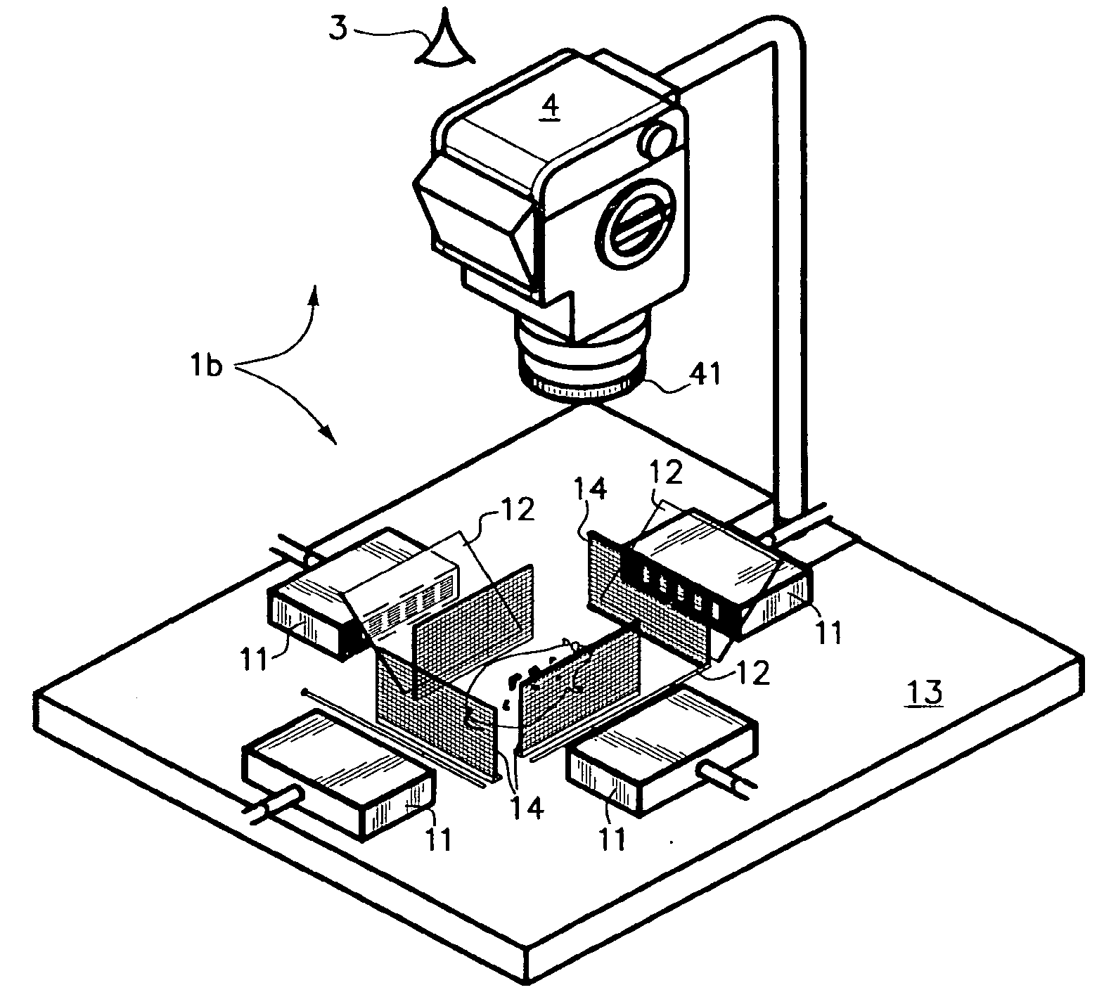
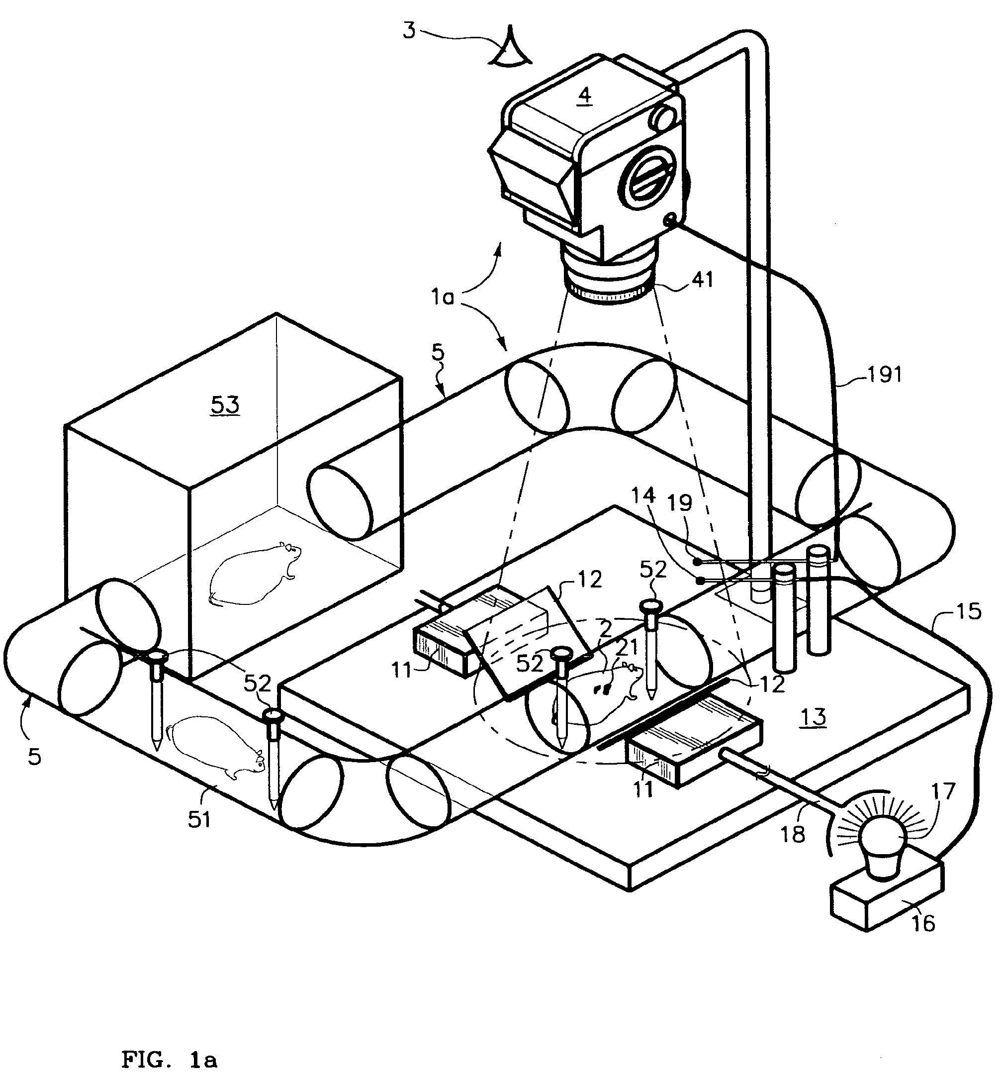
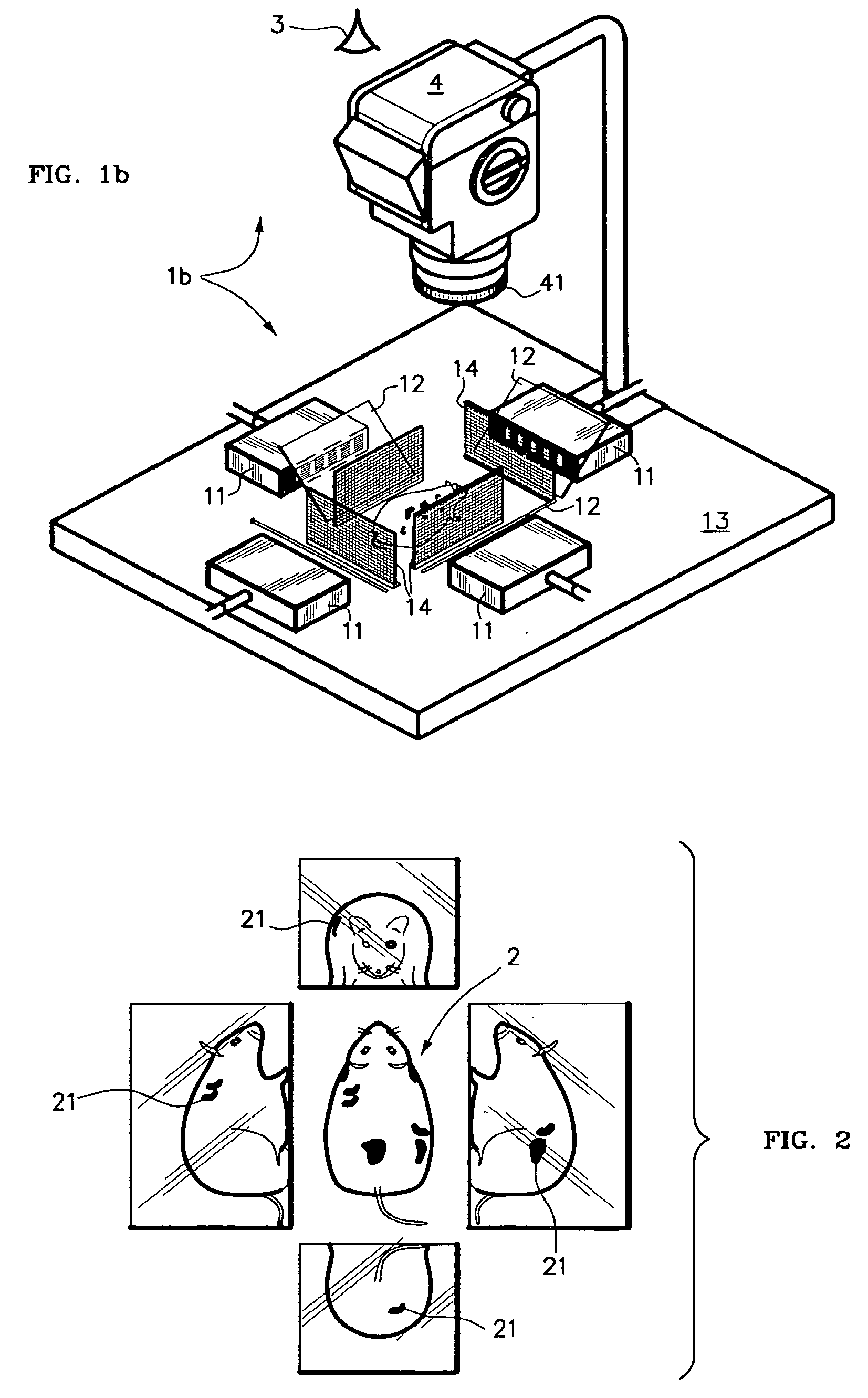
[0090]A diagrammatic view of a first, rudimentary, embodiment of an illumination and viewing apparatus 1a in ac...


PUM

PropertyMeasurementUnit
viewing angleaaaaaaaaaa
fluorescent emissionaaaaaaaaaa
fluorescentaaaaaaaaaa

Abstract

Simultaneous illumination along each of multiple axis for panoramic viewing of a macroscopically-sized specimen along a single viewing axis is realized by dichroic mirrors. Selective control of illumination intensity and / or color(s) of, permissively, each of multiple illuminating lights along multiple illumination axis of the specimen as are induced to fluoresce at corresponding different colors and intensities will all appear clearly visible, and well balanced, in a composite image nonetheless to intrinsically being of greatly differing brightness. Color and intensity calibration of the well-balanced composite image in all its colors and regions may optionally be realized by one or more fluorescent image calibration step wedges. A rule, or grid, scale may be imposed upon the image. The resulting panoramic composite image contains a great deal of quantitative information, being optionally calibrated in any of dimension, scale, overall brightness, the separate intensities of, permissively, each of several separate differently-colored fluorescent emissions.

Description

REFERENCE TO RELATED PATENT APPLICATIONS[0001]The present patent application is related to U.S. patent application Ser. No. 10 / 810,993 (now U.S. Pat. No. 7,173,256) for a FLUORESCENT IMAGE CALIBRATION STEP WEDGE, AND USE THEREOF IN ILLUMINATION FOR FLUORESCENT IMAGING AND AUTOMATIC EXPOSURE. The present patent application is related to U.S. patent application Ser. No. 10 / 788,724 (now U.S. Pat. No. 7,280,726) for CONTROLLED-INTENSITY MULTIPLE-FREQUENCY MULTIPLE-AXIS ILLUMINATION OF MACROSCOPIC SPECIMENS FROM A SINGLE LIGHT SOURCE USING SPECIAL BIFURCATED CABLES.BACKGROUND OF THE INVENTION[0002]1. Field of the Invention[0003]The present invention generally concerns (1) an apparatus, as are commonly but not exclusively used in laboratories, for illuminating and for viewing a macroscopically-sized specimen, for example a mouse, along a viewing axis, and (2) the methods of using such an apparatus.[0004]The present invention particularly concerns viewing, along a single viewing axis at a ...

Claims


Application Information

Patent Timeline
Patent Type & Authority Patents(United States)
IPC IPC(8): G01N21/25
CPCA61B5/0071A61B5/444G01N21/274G01N21/6428G01N21/6456G01N2021/6484G01N2021/6419G01N2021/6421G01N2021/6441
Inventor FOX, JOHN S.
Owner FOX JOHN S
Why Eureka
Try Eureka