Cathodic protection system for non-isolated structures including a microprocessor control

a protection system and microprocessor technology, applied in the field of corrosion control of buried piping, can solve the problems of inability to achieve full cathodic protection, access problems, and practically impossible electrical isolation of piping, and achieve the effect of convenient custom anode design, improved handling, transportation and installation, and quick and easy use for customers

a protection system and microprocessor technology, applied in the field of corrosion control of buried piping, can solve the problems of inability to achieve full cathodic protection, access problems, and practically impossible electrical isolation of piping, and achieve the effect of convenient custom anode design, improved handling, transportation and installation, and quick and easy use for customers

US7582195B2Inactive Publication Date: 2009-09-01BENHAM ROGER A

Image

  • Cathodic protection system for non-isolated structures including a microprocessor control
  • Cathodic protection system for non-isolated structures including a microprocessor control
  • Cathodic protection system for non-isolated structures including a microprocessor control

Examples


Embodiment Construction

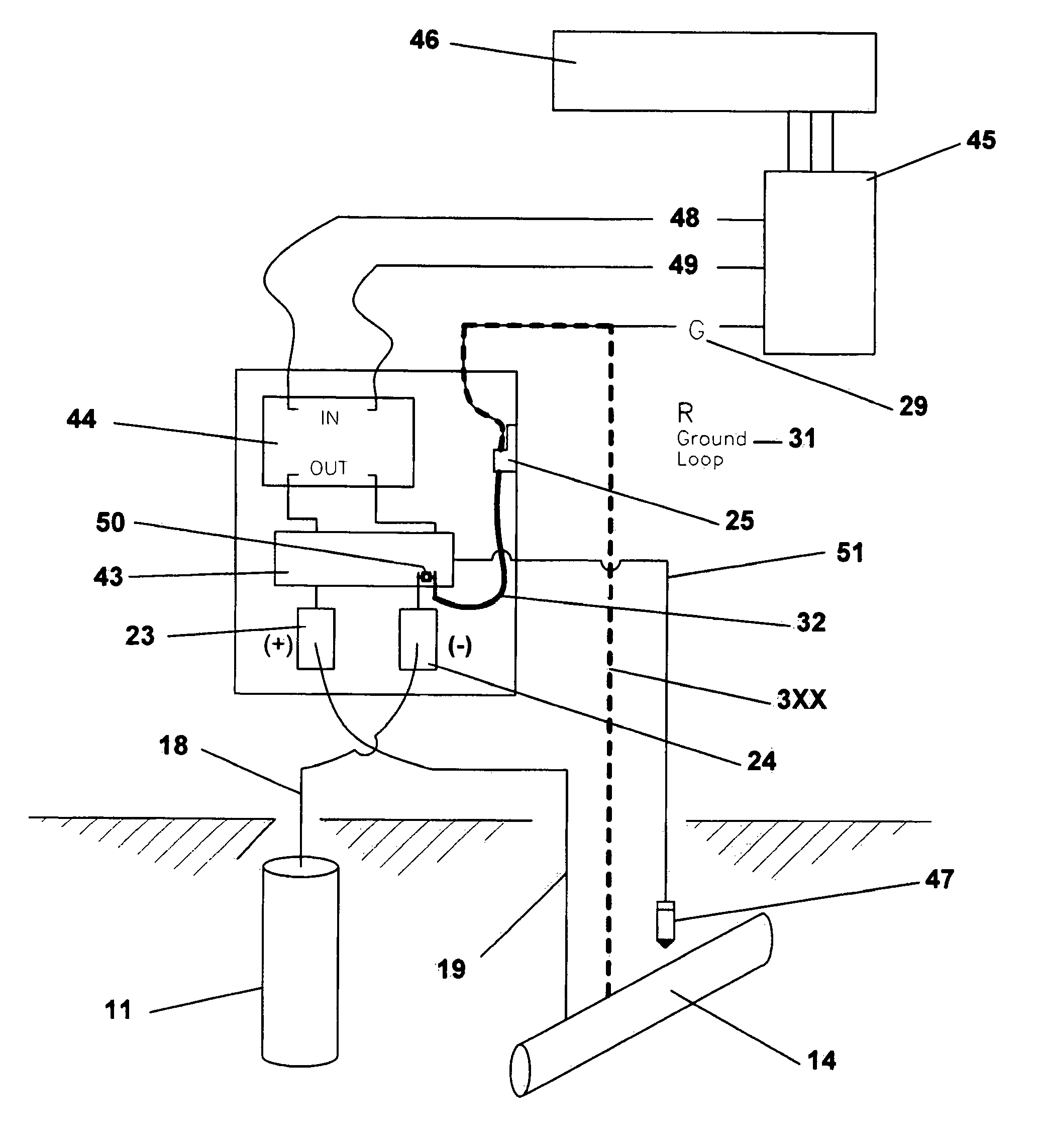
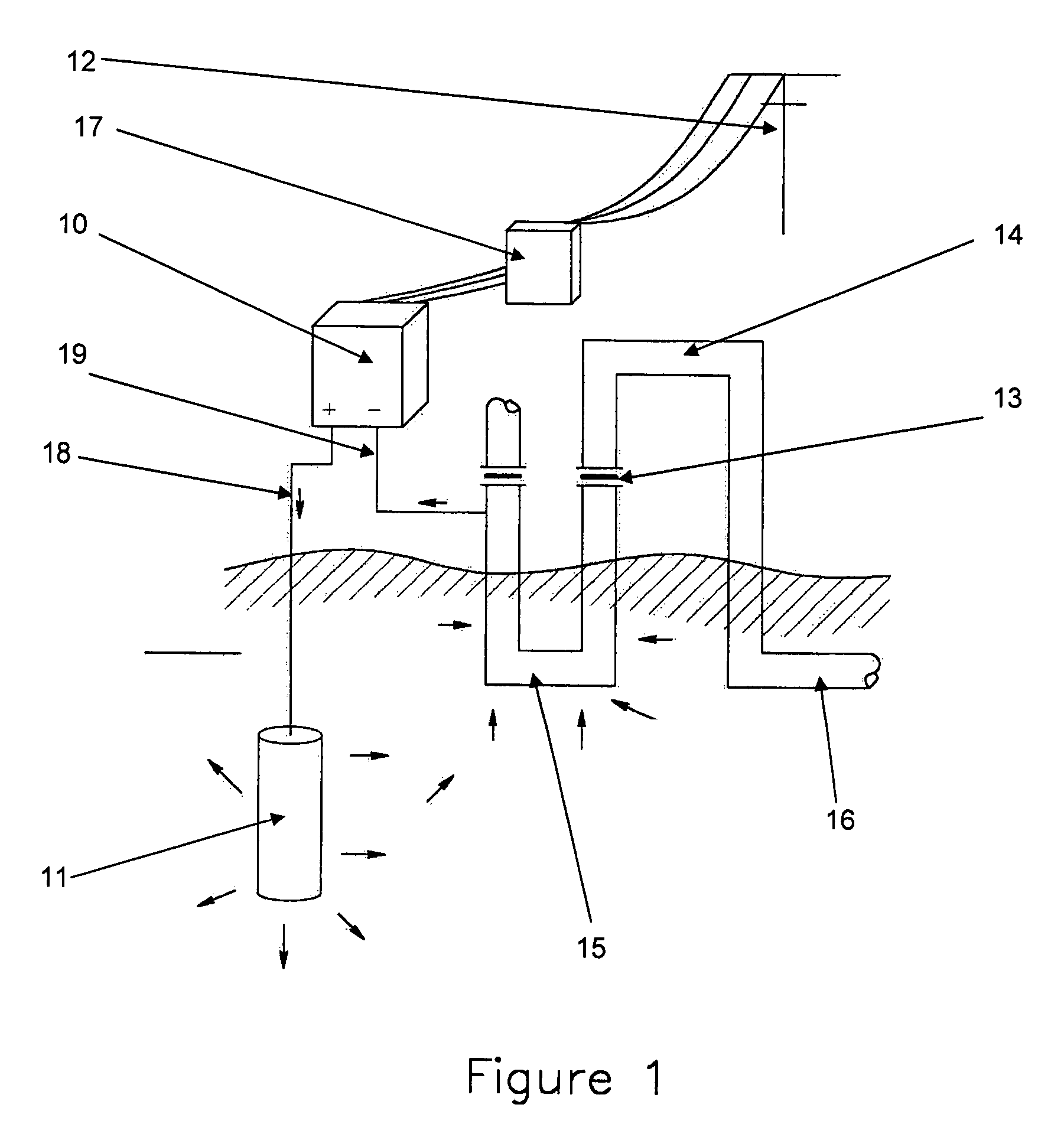
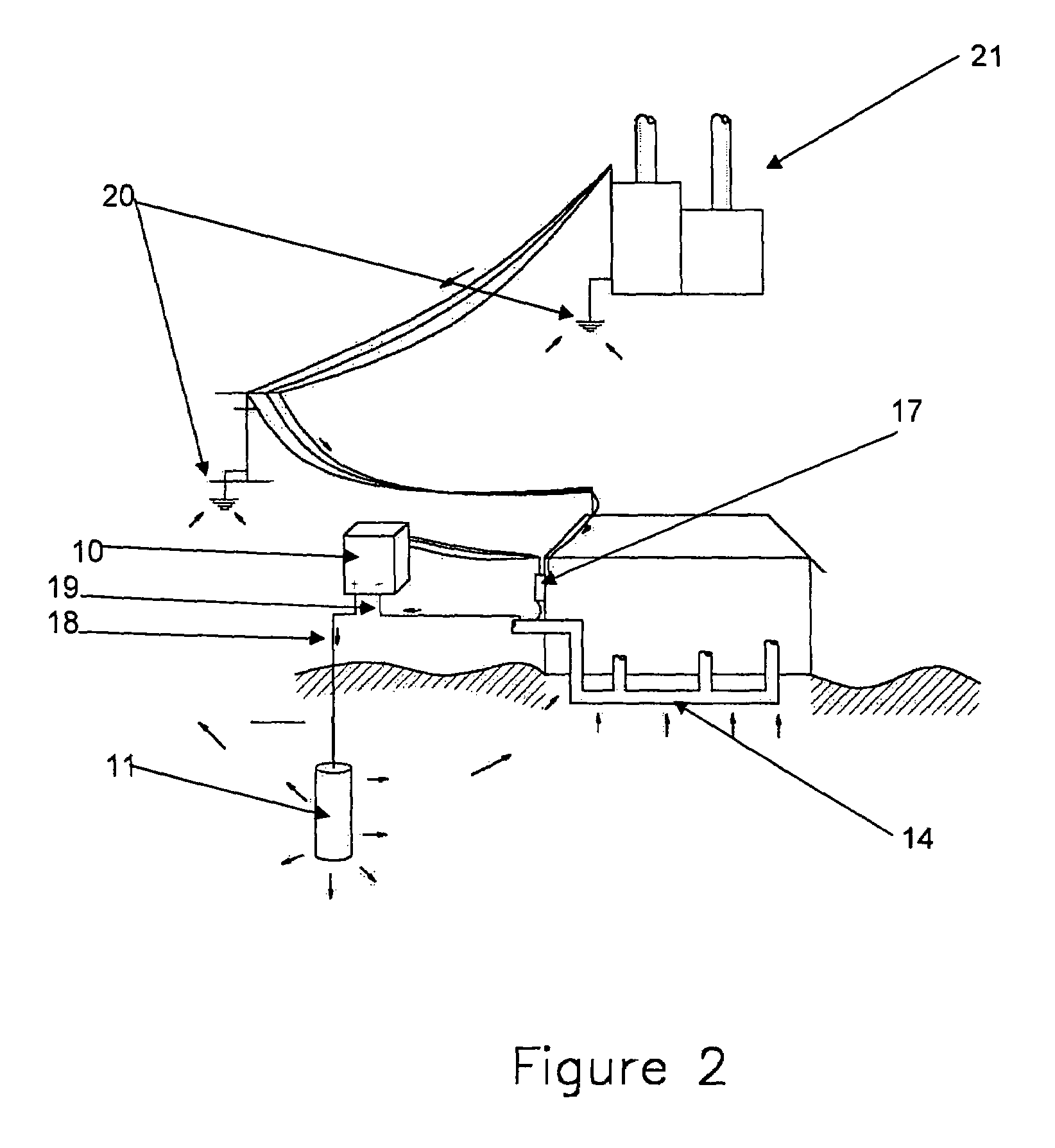
[0048]With reference to FIG. 1 through 9, the cathodic protection system is there illustrated which exemplifies the present invention. The system as shown comprises a DC power supply rectifier, a consumable anode installed in the earth, associated wiring, and the protected piping.

[0049]FIG. 1 shows the typical active, or impressed current cathodic protection system installation, including the DC power supply rectifier 10, the consumable anode-bed 11, associated wiring, AC power source 12, and dielectric insulators 13 to limit electrical current to the intended structure to be protected. The arrows show the direction of the electrical current. The electrical current causes oxidation at the surface of the anode 11 and reduction at the surface of the structure to be protected 14, which is made the cathode in the circuit. The electrical current is contained in the circuit and to the protected section 15 of the structure and is not permitted to impress upon the unprotected section 16 of ...


PUM

PropertyMeasurementUnit
electrical currentaaaaaaaaaa
current levelaaaaaaaaaa
resistanceaaaaaaaaaa

Abstract

An active cathodic protection system, the apparatus comprising a rectifier element with at least one electrical connection to a source of electrical current, the rectifier element associated with a direct current positive (+) output terminal for electrical connection of via an anode connector to a consumable anode, a direct current negative (βˆ’) output terminal for electrical connection via a cathode connector to the structure to be protected, grounding means for electrical grounding of the apparatus and anti-cross connection means for preventing the continuing flow of electrical current when the anode connector is associated with the negative output terminal and the cathode connector is associated with the positive output terminal. The cathodic protection system also includes a microprocessor controlled device for shutting the system if an improper current is sensed. The microprocessor controlled device is also used as a circuit interrupter in combination with a reference cell to determine the existence of the proper cathodic shift used to insure that the system is properly operating.

Description

[0001]The present application is based upon U.S. provisional patent application No. 60 / 433,572, filed Dec. 16, 2002, as well as U.S. patent application Ser. No. 10 / 729,996, filed Dec. 3, 2003, issued as U.S. Pat. No. 7,186,321.BACKGROUND OF THE INVENTION[0002]1. Field of the Invention[0003]The present invention relates to a method of corrosion control for buried piping, and in particular to an impressed current cathodic protection system for protection of isolated and electrically grounded buried or submerged metallic structures, an electrical means of anti-cross-connection, a means of cross-connection warning, a means of controlling DC voltage and current output on a cathodic protection system, a means of maintaining a low resistance ground-bed, and a means of anode and backfill installation and transport.[0004]2. Discussion of Related Art[0005]Cathodic protection is a widely used method of corrosion control for buried or submerged structures. Systems for the cathodic protection of...

Claims


Application Information

Patent Timeline
01 Sep 2009
Publication
US7582195B2
IPC
C23F13/02; C23F13/04
CPC
C23F13/04
Inventors
BENHAM, ROGER A.