Meter bar

a meter bar and meter technology, applied in the field of meter bars, can solve the problems of causing hazard, several potential leakage points, and not without potential weaknesses, and achieve the effects of reducing potential leakage points, minimizing loose parts, and minimizing the number of loose parts

Active Publication Date: 2009-09-08
A Y MCDONALD MFG CO
View PDF5 Cites 1 Cited by
  • Summary
  • Abstract
  • Description
  • Claims
  • Application Information

AI Technical Summary

Benefits of technology

[0010]It is the principal object of the invention to provide a new and improved meter bar for mounting flow measuring meters. More particularly, it is an object of the invention to provide a meter bar assembly that significantly reduces potential leak points in installations using the same, minimizes the number of loose, unattached parts required for a given assembly, thereby reducing the possibility that one or more parts will become lost or otherwise mishandled during the installation process and which may be installed with relative ease even at locations where there are severe spacial constraints.

Problems solved by technology

While conventional meter bars work well for their intended purpose, they are not without their points of potential weaknesses.
As a consequence, several potential points of leakage are present.
Needless to say, when a combustible material such as natural gas or other manufactured gas is being metered, leakage creates a hazard, particularly if the meter bar with the meter mounted thereon is located indoors or within a structure that minimizes the possibility of dissipation of any small leakage to the ambient.
Furthermore, in some situations, connections to the upstream side of the inlet conduit 16 or the downstream side of the outlet conduit 28 may be made difficult by spacial limitations.

Method used


Image

  • Meter bar
  • Meter bar
  • Meter bar

Examples


Embodiment Construction

[0027]While the invention herein disclosed is primarily intended for use in natural gas distribution systems, it may be used in other fluid distribution systems wherein flow of the fluid being distributed is to be monitored by a meter, and no limitation to gas systems is intended except insofar as stated in the appended claims.

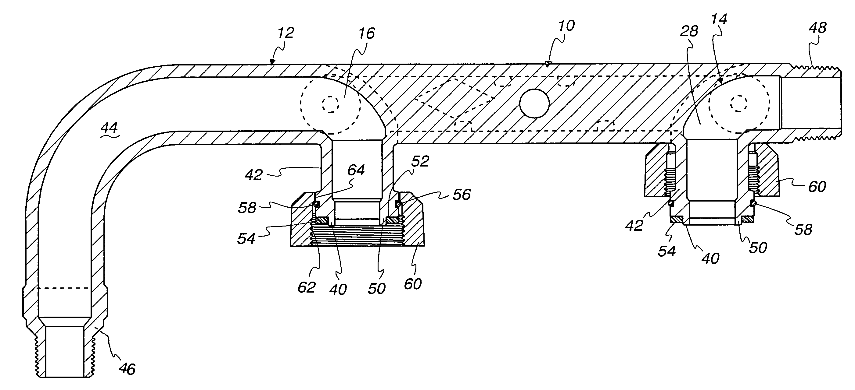
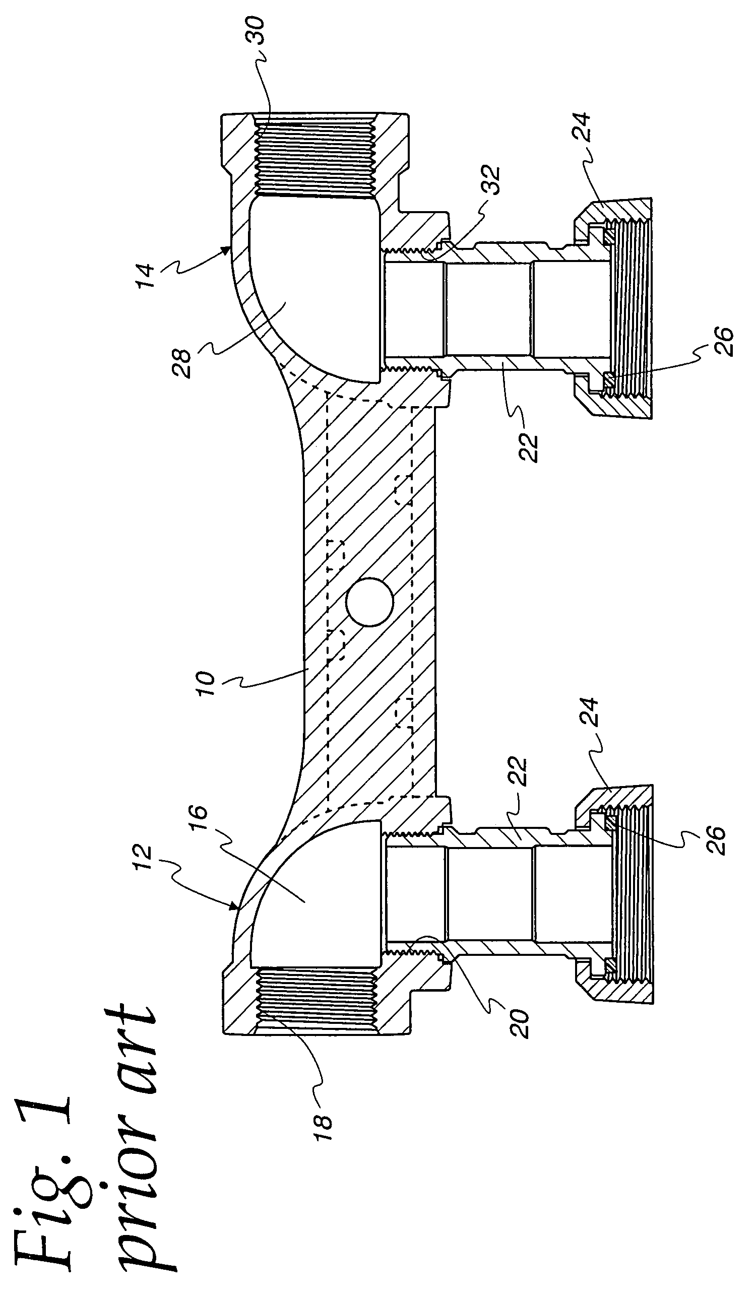
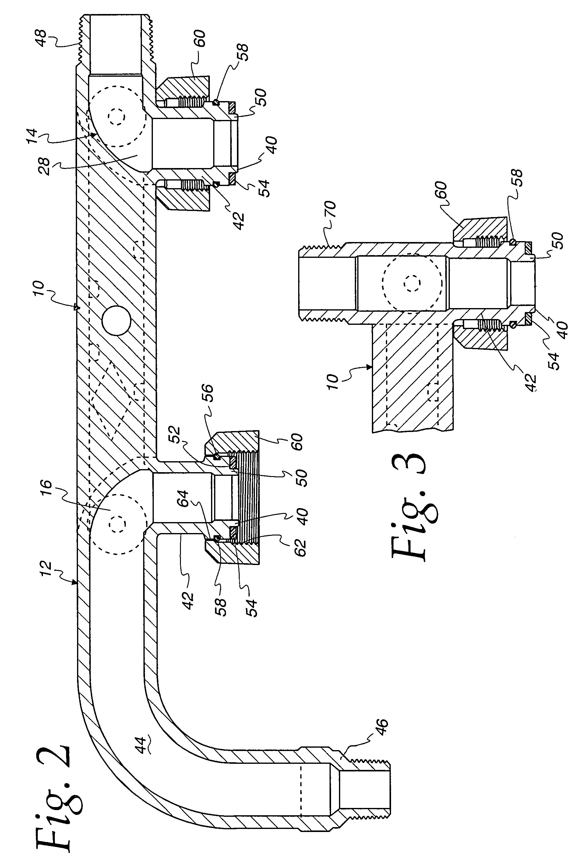
[0028]Turning first to FIG. 2, a first embodiment of a meter bar made according to the invention will be described. As in the prior art, the same includes a central bar section, generally designated 10, which typically will have a cross section much like an I-beam. At one end, specifically the right end as shown in FIG. 2, an outlet section, generally designated 14, is located while at the left hand and as shown in FIG. 2, the central section 10 terminates at an inlet section 12. The inlet section 12 includes an inlet conduit 16 which, at one end 40, includes an integral tailpiece 42. At its other end, the inlet conduit 16 includes an elongated, curved section...


PUM


Abstract

Potential leakage points are avoided, mishandling or loss of loose, unattached parts minimized and installation in tight places facilitated by a meter bar of elongated cast metal structure having a central bar, an outlet conduit section and an inlet conduit section, both integral with the meter bar. The inlet and outlet sections may include integral tail pieces and an upstream end of the inlet section includes an elongated, downwardly curved conduit to eliminate the need for the use of elbows, pipes or nipples, etc.

Description

FIELD OF THE INVENTION[0001]This invention relates to a meter bar, and more particularly, to a meter bar assembly that is adapted to be connected into a fluid handling system, such as a gas distribution system, for mounting a fluid flow measuring meter in the system.BACKGROUND OF THE INVENTION[0002]Meter bars are common in various types of fluid distribution systems, most notably, natural gas and other manufactured gas distribution systems. In the usual case, the bar is disposed generally horizontally and supports a meter which meters the flow of the fluid through the system. In the usual case, the meter bar will have an inlet end and an outlet end and both have conduits internal to the bar itself. At the inlet end, one port for the conduit will be connected to the fluid supply and the other connected to the inlet side of the meter. At the outlet end of the bar, the outlet of the meter will be connected to one of the ports and the other port at the outlet end will be connected to th...

Claims


Application Information

Patent Timeline
Patent Type & Authority Patents(United States)
IPC IPC(8): F16K43/00
CPCF16L19/0231Y10T137/5997
Inventor GOHDE, JON
Owner A Y MCDONALD MFG CO
Why Eureka
Try Eureka