
Discharge valve system of scroll compressor

Active Publication Date: 2006-05-11
LG ELECTRONICS INC
View PDF1 Cites 49 Cited by
  • Summary
  • Abstract
  • Description
  • Claims
  • Application Information

AI Technical Summary

Benefits of technology

[0026] Therefore, an object of the present invention is to provide a discharge valve system of a scroll compressor capable of maximizing a discharge amount of gas compressed in a low pressure ratio operation and capable of minimizing the number of assembly processes by simplifying components.

Problems solved by technology

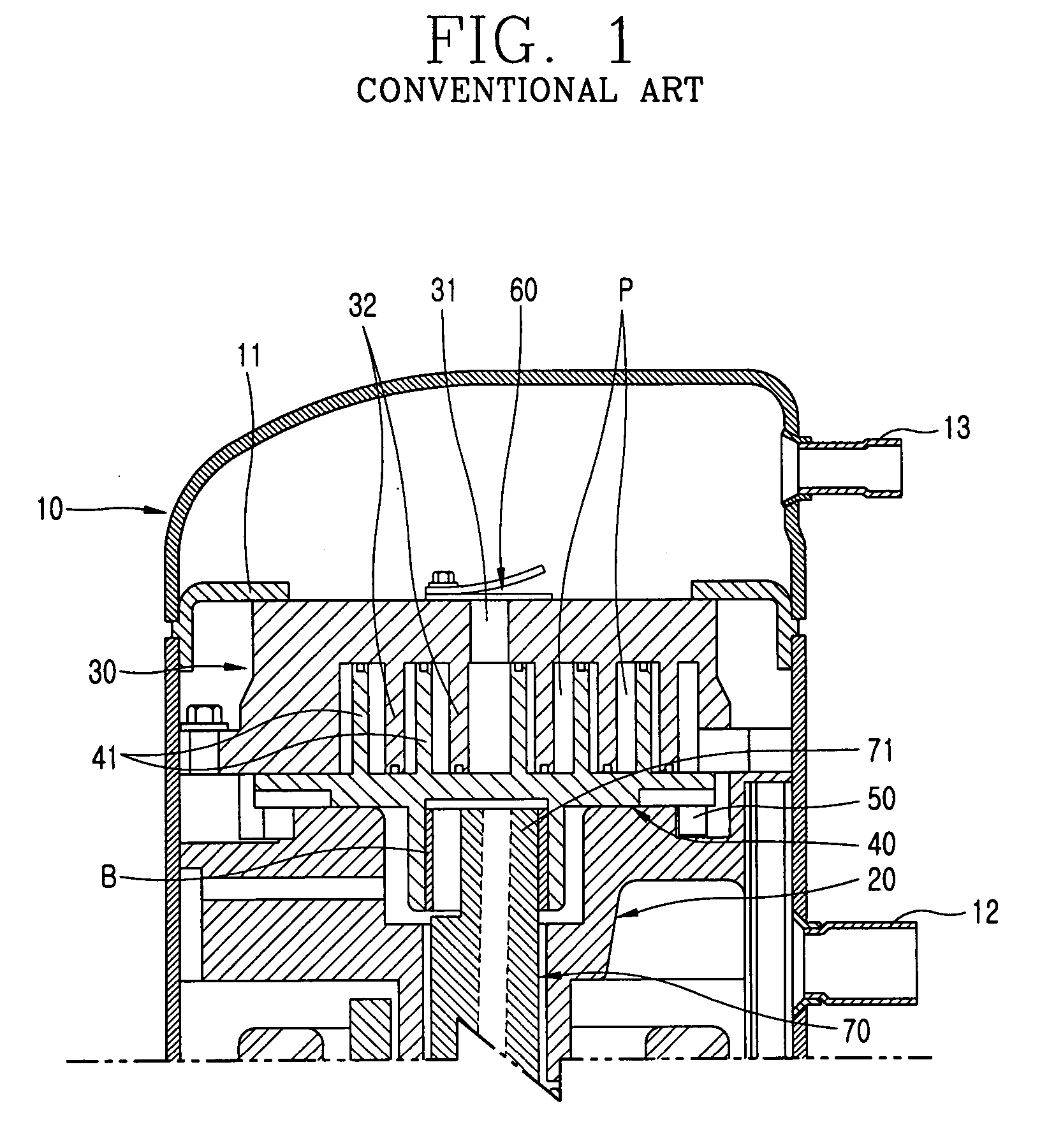
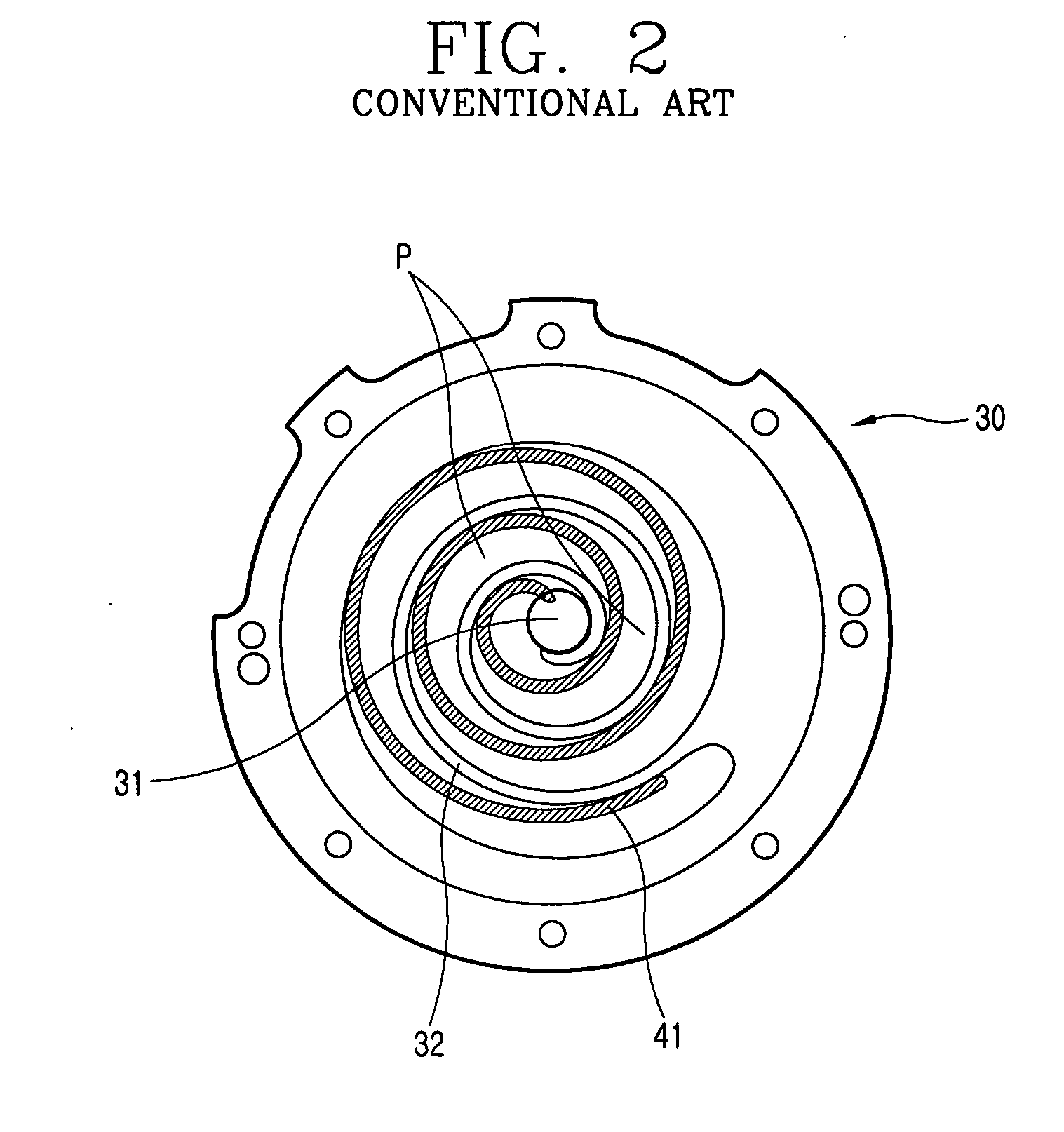
However, in the conventional discharge valve system of a scroll compressor, the size of the first and second double bypass holes 33 can not be increased.
According to this, gas compressed in a low pressure ratio can not be sufficiently discharged through the first and second bypass holes.
According to this, there is a difficulty in mass-producing the discharge valve system, an assembly productivity is lowered, and a fabrication cost is increased.

Method used


Image

  • Discharge valve system of scroll compressor
  • Discharge valve system of scroll compressor
  • Discharge valve system of scroll compressor

Examples


Embodiment Construction

[0037] Reference will now be made in detail to the preferred embodiments of the present invention, examples of which are illustrated in the accompanying drawings.

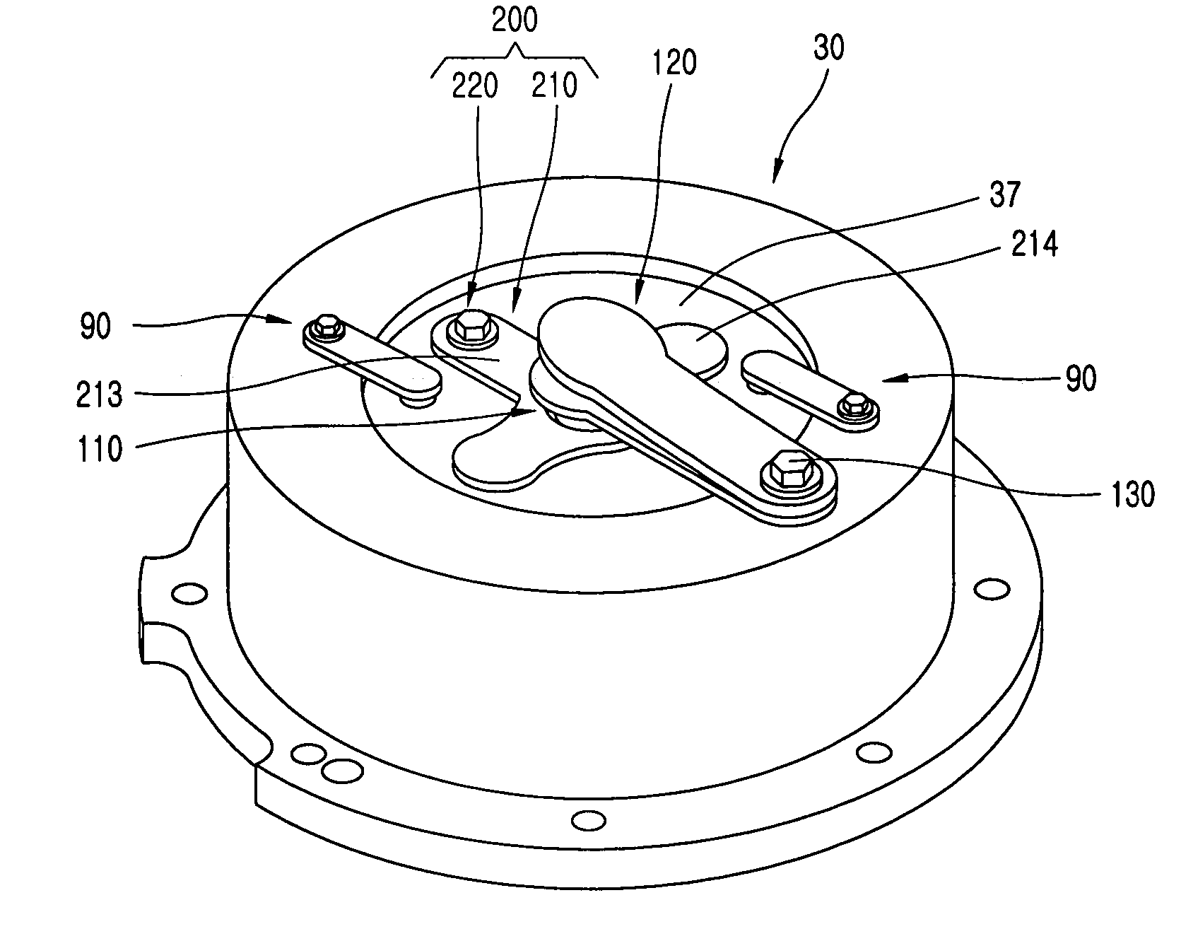
[0038]FIGS. 5, 6, and 7 are respectively a perspective view, a plane view, and a front sectional view showing a fixed scroll having a discharge valve system of a scroll compressor according to one embodiment of the present invention.

[0039] As shown, in the discharge valve system of the scroll compressor according to the present invention, a discharge hole 31 is penetratingly formed at a fixed scroll 30 constituting a compression part, and discharge bypass holes 33 are penetratingly formed at the fixed scroll 30 to be positioned at both sides of the discharge hole 31.

[0040] The discharge hole 31 is positioned at a center portion of the fixed scroll 30, and a protruded valve seat portion 36 having a certain width, an outer diameter, and a height is formed at an edge of the discharge hole 31. The protruded valve seat portio...


PUM


Abstract

A discharge valve system of a scroll compressor comprises: a fixed scroll having a discharge hole and discharge bypass holes; a discharge valve assembly mounted at the fixed scroll, for opening and closing the discharge hole by a pressure difference; and an integral bypass valve assembly mounted at the fixed scroll, for opening and closing the bypass holes and interworking the discharge valve assembly. According to this, a discharge amount of gas is maximized in a low pressure ration driving of the scroll compressor thereby to enhance a discharge efficiency. Also, the number of components is greatly reduced thus to reduce a fabrication cost. Also, the number of assembly processes is greatly reduced thereby to enhance an assembly productivity.

Description

1. FIELD OF THE INVENTION [0001] The present invention relates to a scroll compressor, and more particularly, to a discharge valve system of a scroll compressor capable of maximizing a discharge amount of gas compressed in a low pressure ratio operation and capable of minimizing the number of assembly processes by simplifying components. 2. DESCRIPTION OF THE CONVENTIONAL ART [0002] Generally, a compressor converts electric energy into kinetic energy, and compresses refrigerant gas by the kinetic energy. The compressor is a core component constituting a refrigerating cycle system, and includes various kinds such as a rotary compressor, a scroll compressor, a reciprocal compressor, etc. according to a compression mechanism for compressing a refrigerant. The compressors are used in a refrigerator, an air conditioner, a showcase, etc. The scroll compressor is divided into a motor part for generating a rotational force; and a compression part for sucking, compressing, and discharging ga...

Claims


Application Information

Patent Timeline
IPC IPC(8): F01C1/02F01C1/063F04C2/00F03C2/00F04C18/00F03C4/00
CPCF04C28/16F04C29/128F04C18/02
Inventor LEE, BYEONG-CHULYOO, BYUNG-KIL
Owner LG ELECTRONICS INC
Learn More