Magnetic recording device including a thermal proximity sensor

a thermal proximity sensor and magnetic recording technology, applied in the field of magnetic recording devices, can solve the problems of compromising the life of readers, most conventional recording systems do not provide reliable approaches to monitoring the hms in-situ, and temporal modulation of the hms

Inactive Publication Date: 2009-09-15
SEAGATE SINGAPORE INT HEADQUARTERS PTE LTD
View PDF17 Cites 59 Cited by
  • Summary
  • Abstract
  • Description
  • Claims
  • Application Information

AI Technical Summary

Problems solved by technology

Maintaining a constant head-to-medium spacing (HMS) is important throughout the life of the magnetic recording system, since the close proximity of the head to the medium makes the drive susceptible to reliability issues that could lead to temporary modulation of the HMS.
Most conventional recording systems do not provide reliable approaches to monitoring the HMS in-situ.
This can lead to compromised reader life and, because the reader is highly magnetoresistive, can also make it difficult to differentiate between the thermally and magnetically induced components of resistance change in the reader.

Method used


Image

  • Magnetic recording device including a thermal proximity sensor
  • Magnetic recording device including a thermal proximity sensor
  • Magnetic recording device including a thermal proximity sensor

Examples


Embodiment Construction

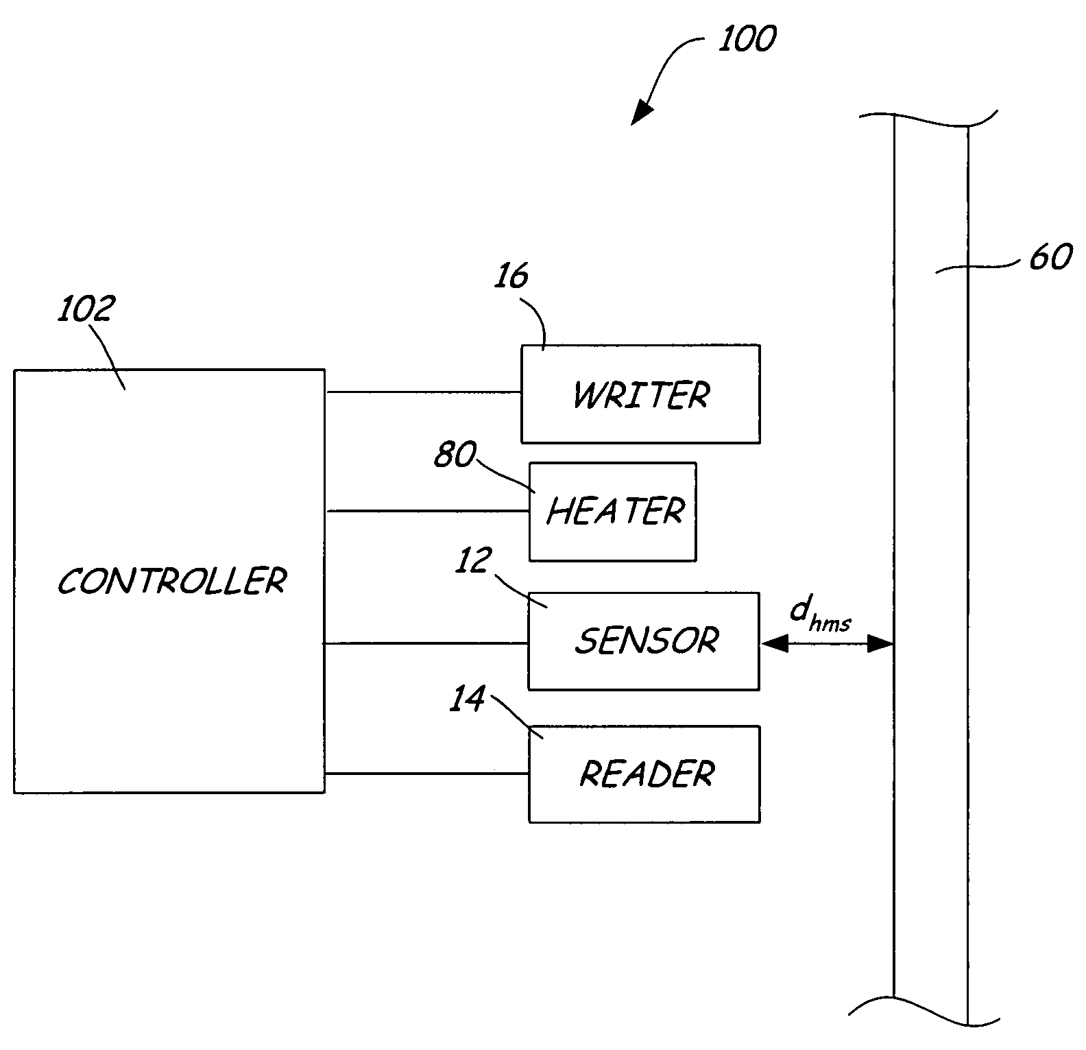
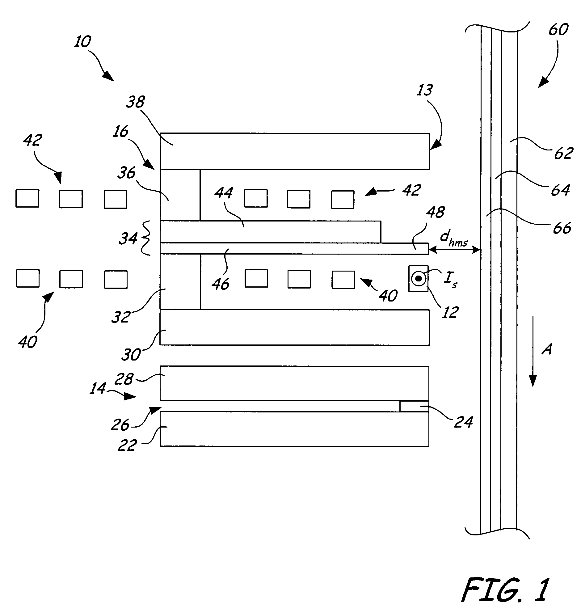
[0014]FIG. 1 is a cross-sectional view of transducing head 10 including thermal proximity sensor 12 to provide signals related to the head-to-medium spacing (HMS) of transducing head 10. Sensor 12 will be described in more detail with regard to FIGS. 2-6. Transducing head 10 includes reader 14 and writer 16 that define medium confronting surface 18. Reader 14 includes bottom shield structure 22, read element 24, read gap 26, and top shield structure 28. Writer 16 includes first return pole 30, first magnetic stud 32, main pole 34, second magnetic stud 36, second return pole 38, first conductive coil 40, and second conductive coil 42. Main pole 34 includes main pole body 44, yoke 46, and main pole tip 48.

[0015]Reader 14 and writer 16 are each multi-layered devices, and writer 16 is stacked on reader 14 in a piggyback configuration in which layers are not shared between the two elements. In other embodiments not illustrated, reader 14 and writer 16 may be arranged in a merged-head con...


PUM

PropertyMeasurementUnit
distance dspaaaaaaaaaa
operating temperature resistanceaaaaaaaaaa

Abstract

A system includes a magnetic device for writing to and reading from a magnetic medium and a sensor disposed adjacent to the magnetic device and proximate to the magnetic medium. The sensor generates signals related to thermal variations in the sensor caused by changes in a distance between the magnetic device and the magnetic medium.

Description

BACKGROUND OF THE INVENTION[0001]The present invention relates to magnetic devices. More particularly, the present invention relates to managing the head-to-medium spacing (HMS) in a recording system using thermal proximity measurement.[0002]In magnetic recording systems, a rapid increase in the areal density of magnetic media has led to reduction of the spacing between the head and the medium down to less than 10 nm. Maintaining a constant head-to-medium spacing (HMS) is important throughout the life of the magnetic recording system, since the close proximity of the head to the medium makes the drive susceptible to reliability issues that could lead to temporary modulation of the HMS. Most conventional recording systems do not provide reliable approaches to monitoring the HMS in-situ.[0003]The difference in temperature between the head and the medium results in heat transfer during operation, which may be represented by:[0004]q=Ka⁢Δ⁢⁢Th+cTp(Equation⁢⁢1)where q is the amount of heat...

Claims


Application Information

Patent Timeline
Patent Type & Authority Patents(United States)
IPC IPC(8): G11B21/02
CPCG11B5/1278G11B5/3133G11B5/6064G11B5/40G11B5/6005G11B5/314G11B5/607
Inventor ROY, MALLIKAGAO, KAIZHONGJIN, INSIKFITZPATRICK, WILLIAM BRUCEDAKROUB, HOUSAN S.MAO, SININGXUE, SONG S.LAKE, JEFFREY HOWARDSETIADI, DADI
Owner SEAGATE SINGAPORE INT HEADQUARTERS PTE LTD
Why Eureka
Try Eureka