
Sealed rolling bearing

a rolling bearing and seal technology, applied in the direction of bearing components, shafts and bearings, cooking-vessel materials, etc., can solve the problems of reducing the sealability of the bearing space, the lips and/or sliding contact surfaces are worn by the mud contained in such muddy water, and the damage to the first or the second part of the bearing, so as to prevent the damage or shifting of the first, prevent the deterioration of the sealability, and ensure the sealability of the second portion

Active Publication Date: 2009-09-22
NTN CORP
View PDF22 Cites 30 Cited by
  • Summary
  • Abstract
  • Description
  • Claims
  • Application Information

AI Technical Summary

Benefits of technology

The present invention provides a sealed rolling bearing that has high sealability even in environments where muddy water splashes. The bearing includes first and second contact seals that stop muddy water from reaching and damaging the lips and sliding contact surfaces of the seals. The lips are made of elastic material and in line contact with the sliding contact surfaces to prevent any muddy water from entering the bearing space. The bearing also includes a retainer that reduces the axial length of the bearing. These features ensure the bearing's performance and durability in various environments.

Problems solved by technology

Thus, such rolling bearings tend to be splashed with muddy water and hit by flying stones.
For such a rolling bearing, if the rolling bearing disclosed in Reference 1 were to be used, splashed muddy water would adhere to the lips of the contact seals or the sliding contact surfaces of the inner or outer ring, causing the lips and / or the sliding contact surfaces to become worn by mud contained in such muddy water.
This extremely lowers the sealability of the bearing space.
However, since there exists a gap between each shield and the inner or outer ring, muddy water tends to infiltrate through the labyrinth gaps into gaps between the shields and the contact seals.
When such muddy water, of which the concentration of mud has increased, adheres to the lips of the contact seals and the sliding contact surfaces, these portions will become worn.
This lowers sealability of the bearing space.

Method used


Image

  • Sealed rolling bearing
  • Sealed rolling bearing
  • Sealed rolling bearing

Examples


Embodiment Construction

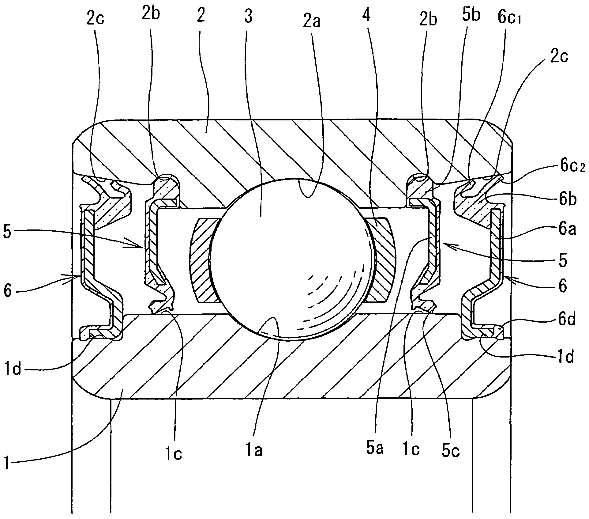
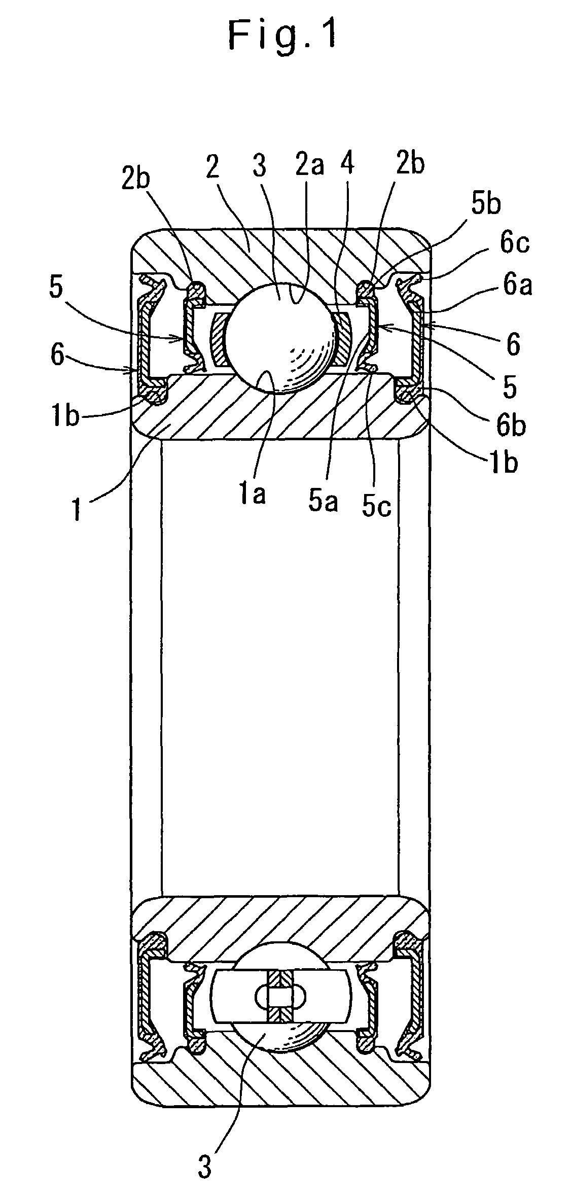
[0029]Now referring to the drawings, FIGS. 1 and 2 show the sealed rolling bearing according to the first embodiment of the present invention, which comprises, as shown in FIG. 1, an inner ring 1 and an outer ring 2 formed with raceways 1a and 2a, respectively, rolling elements in the form of balls 3 disposed between the raceways 1a and 2a, and a retainer 4 retaining the balls 3. The inner and outer rings 1 and 2 define a bearing space therebetween in which are disposed the balls 3 and the retainer 4. An axially inner contact seal 5 and an axially outer contact seal 6 are provided on either side of the bearing space, thereby sealing the bearing space.

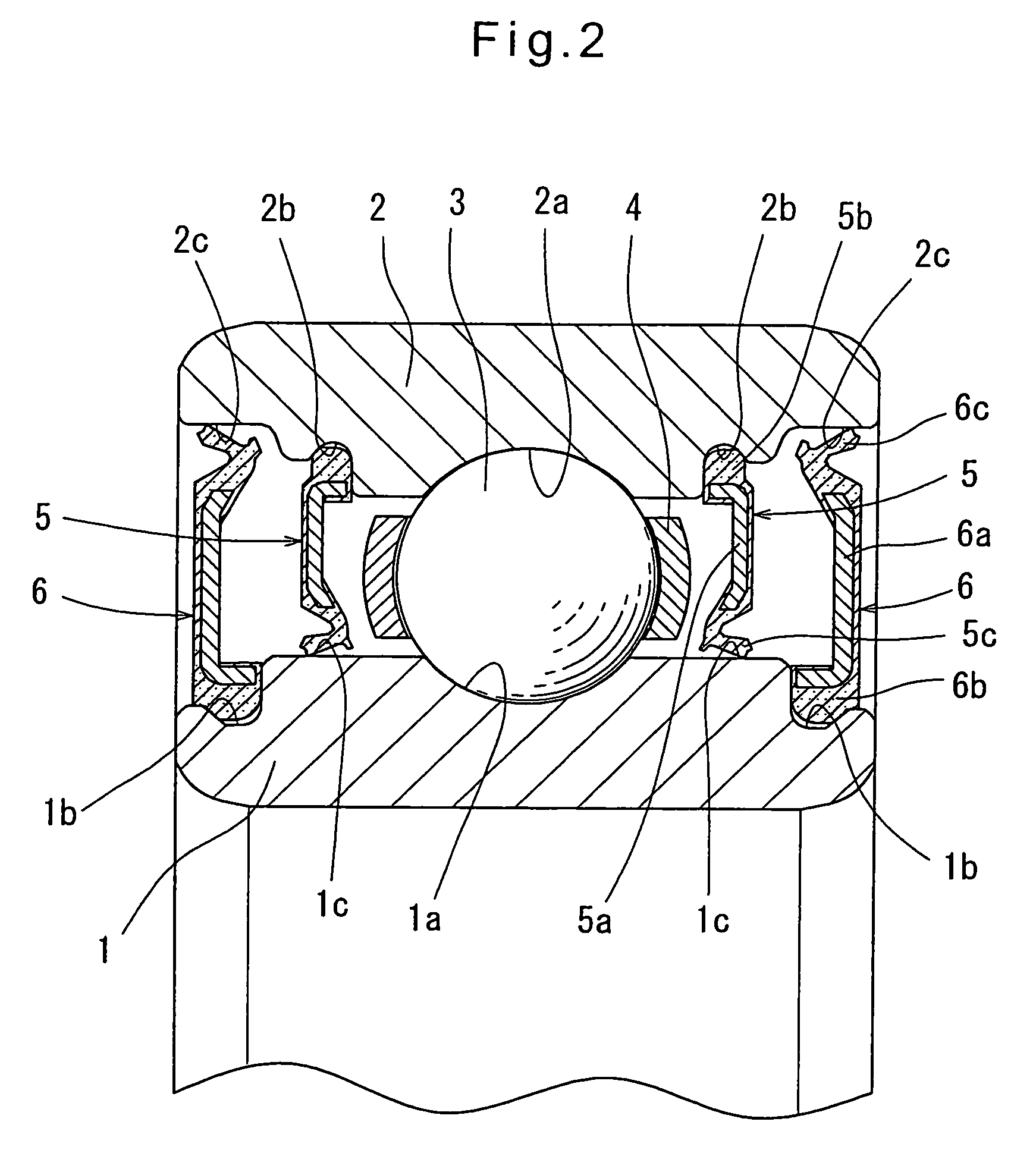
[0030]As shown in FIG. 2, each of the contact seals 5 and 6 comprises metallic core 5a, 6a having an L-shaped section, and an elastic member 5b, 6b. Each of the inner contact seals 5 is fixed to the outer ring 2 by having its elastic member 5b partially fitted in a groove 2b formed in the radially inner surface of the outer ring 2 with ...


PUM


Abstract

A sealed rolling bearing includes an inner ring and an outer ring defining a bearing space therebetween. Axially inner and outer contact seals are provided on each side of the bearing space to seal the bearing space. The axially outer contact seals stop any splashed muddy water, thereby keeping the lips of the axially inner contact seals and their sliding contact surfaces free of muddy water. This prevents the lips of the axially inner contact seals and their sliding contact surfaces from becoming worn by muddy water. The axially inner contact seals thus maintain high sealability even if the bearing is used in environments where muddy water splashes.

Description

BACKGROUND OF THE INVENTION[0001]The present invention relates to a sealed rolling bearing having a bearing space between inner and outer rings and which is sealed with contact seals.[0002]As rolling bearings used in environments where dust flies and water splashes, sealed rolling bearings are typically used. The sealed rolling bearings have their bearing space sealed with contact seals to prevent entry of dust and water into the bearing space. The contact seals include lips that are in sliding contact with the inner or outer ring to seal the bearing space.[0003]Some of such sealed rolling bearings include two such contact seals each provided on one side of the bearing space (as disclosed in JP utility model publication 7-10555A (FIG. 1); Reference 1). Other sealed rolling bearings include, besides such two contact seals, non-contact shields each provided outside of one of the two contact seals (as disclosed in JP utility model publication 8-3710A (FIGS. 1 and 2); Reference 2, and J...

Claims


Application Information

Patent Timeline
Patent Type & Authority Patents(United States)
IPC IPC(8): F16C33/76
CPCF16C33/7896F16C33/7889F16C33/7859F16C19/06F16C33/7856F16C2326/06A47J37/067A47J36/04
Inventor TSUJIMOTO, TAKASHI
Owner NTN CORP
Features
  • Generate Ideas
  • Intellectual Property
  • Life Sciences
  • Materials
  • Tech Scout
  • Unparalleled Data Quality
  • Higher Quality Content
  • 60% Fewer Hallucinations
Learn More