Electronic device housing with integrated user input capability

a technology of electronic devices and user input, applied in the direction of instruments, pulse techniques, keyboard-like devices, etc., can solve the problems of user inability to wear gloves when using the device, complicated manufacturing processes, and high cos

Active Publication Date: 2009-09-29
CHENG UEI PRECISION IND CO LTD +1
View PDF15 Cites 45 Cited by
  • Summary
  • Abstract
  • Description
  • Claims
  • Application Information

AI Technical Summary

Benefits of technology

[0011]In comparison with traditional switches, this invention allows the product design to be clean and free of lines and seams associated with conventional buttons. In contrast to recently popular touch switches that detect the presence of a human finger or a conductive object, this approach is also able to work with non-conductive objects such as a person wearing a glove and measure the level of force applied by the user in a proportional sense.

Problems solved by technology

One of the limitations of such proximity sensors is that the user cannot wear gloves when using the device.
This approach requires the device to incorporate several separate components that have to be assembled together to make it work, making manufacturing processes quite complicated and costly.

Method used


Image

  • Electronic device housing with integrated user input capability
  • Electronic device housing with integrated user input capability
  • Electronic device housing with integrated user input capability

Examples


second embodiment

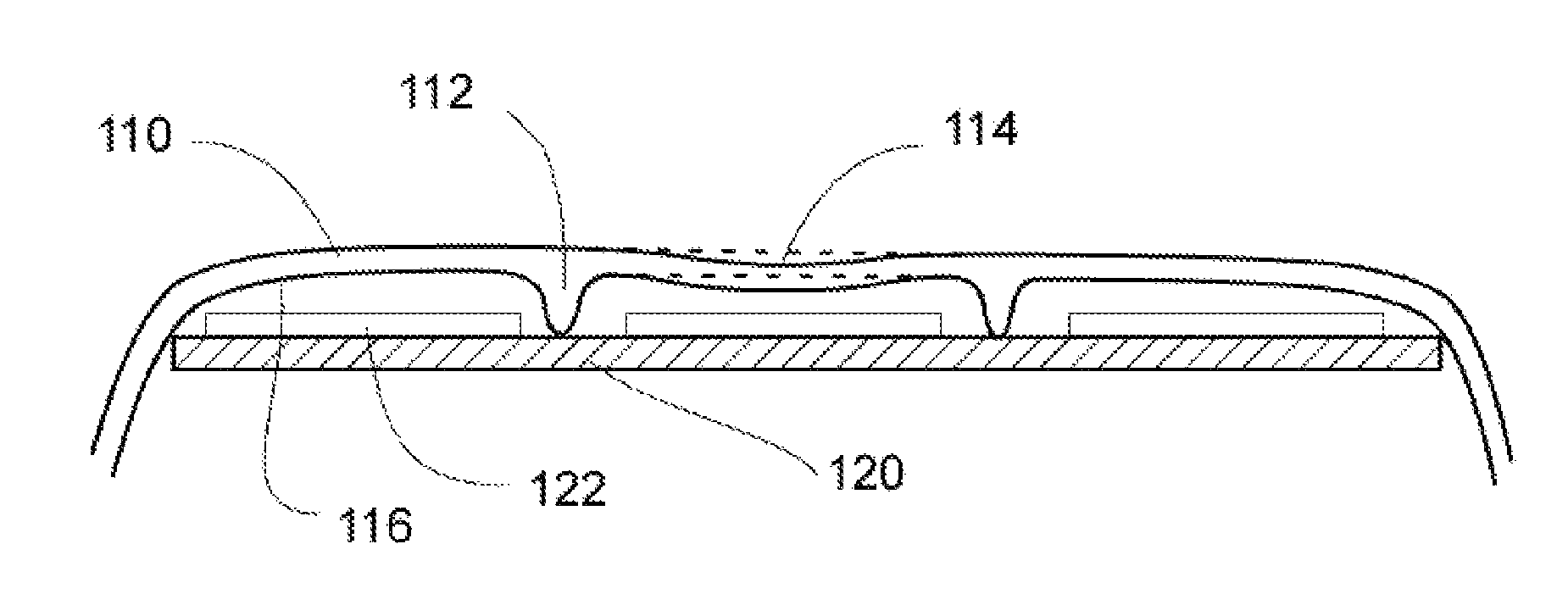
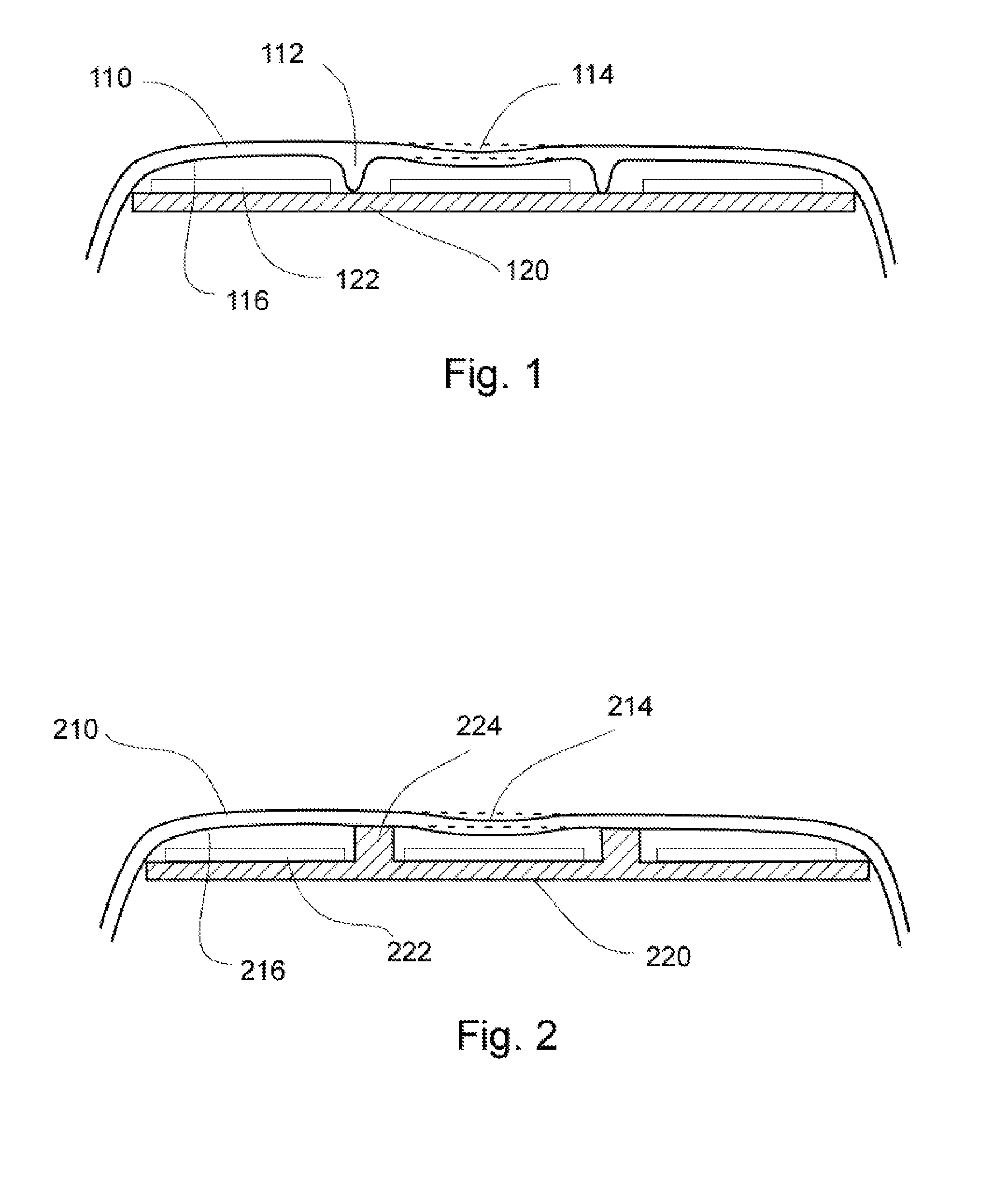
[0027]FIG. 2 shows the invention where the electronic housing 210 has a contact force-sensitive deformable zone made sufficiently thin such that when a user applies force over that zone, the housing deflects as shown from the normal undeflected state indicated by a pair of dashed lines 214. The capacitance sensor is formed between the inside conductive surface 216 of the housing 210 (first conductive layer) and the second conductive layer 222 of the rigid base 220. The thin housing could be made from plastic or metal and is supported by a linear support means such as columns 224 with an air gap separating it from the rigid base 220. In this embodiment, linear support means are incorporated into the rigid base 220 as opposed to being a part of the housing 210. The sections between the support means form the buttons of the user input zone.

first embodiment

[0028]As with the first embodiment, the inside surface of the housing 210 is metalized or painted with a conductive material if it isn't made entirely from a conductive material already. It is then connected to the ground reference of a circuit that can measure the capacitance between by the first conductive layer 216 and second conductive layer 222. The second conductive layer 222 can be formed by printed circuit board 220 etching method or by printing a conductive paint over the base 220.

[0029]In a further development of that concept, the linear support means can be made rigid or compressible and can also be optionally made as a separate part altogether, such as for example a plurality of rubber strips. Further, more than one of such linear support means can be used together to resist deflection of the housing over a single button area (not shown).

third embodiment

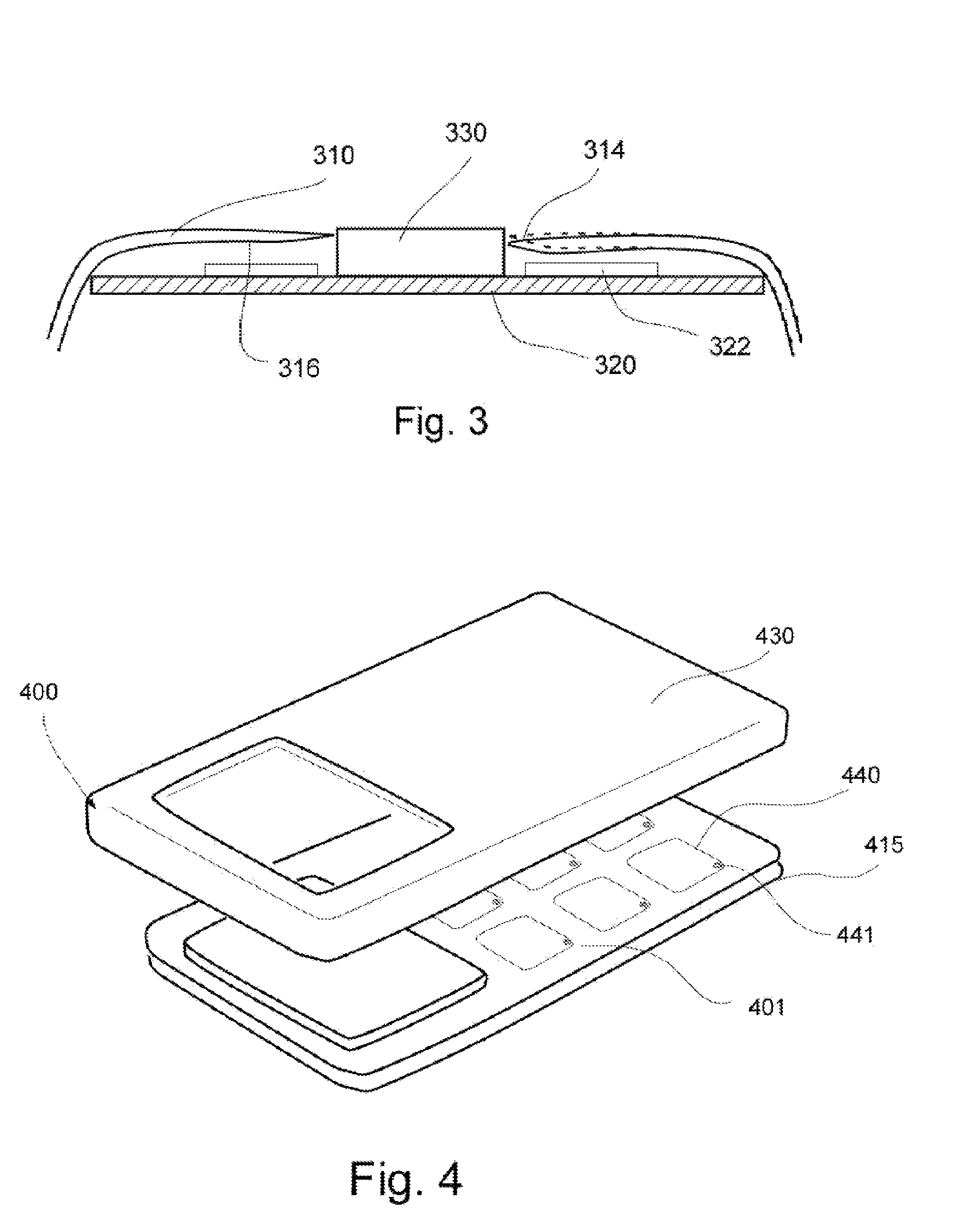
[0030]FIG. 3 shows the invention where the electronic housing 310 is suspended in a cantilever fashion away from the opening in the housing such that when a user applies force on a user input zone 310, the housing deflects as shown from the nominal non-compressed state indicated by dashed lines 314. The thin housing could be made from plastic or metal. This embodiment shows an element 330 protruding from the rigid base 320 through the opening in the housing 310. This element may be a display module, a high resolution input device or may serve other function for the electronic device.

[0031]The inside surface of the housing 310 is again metalized or painted with a conductive material if it isn't made from a conductive material and connected to the ground reference of a circuit that can measure the capacitance formed by 316 and electrode 322. The electrode 322 can be formed by printed circuit board 320 etching method or by printing a conductive paint over a base 320.

[0032]Optional line...


PUM


Abstract

An electronic device housing with a seemless user input zone that measures the level of force applied by the user is described. It is particularly advantageous when used with small hand-held consumer electronic devices such as mobile phones, PDAs, game- and media players. A housing for an electronic device includes a seamless user input zone defining a contact force-sensitive deformable area. A capacitance sensor is formed between the conductive inside surface of the housing and the electrode of the rigid base facing that inside surface. Linear support means such as columns support the housing away from the rigid base defining an air gap. Capacitance measurement circuit is deployed to detect the location and force applied by the user onto the housing and send a user input signal to the electronic device.

Description

CROSS-REFERENCE DATA[0001]This application claims the priority of the U.S. Provisional Patent Application No. 60 / 792,379 filed Apr. 14, 2006 with the same title and incorporated herein in its entirety by reference.FIELD OF THE INVENTION[0002]The present invention generally relates to electronic devices with housings incorporating user input means based on contact force sensing. More specifically, the invention relates to a hand-held electronic device with a portion of a housing adapted to serve as a contact force-sensitive user input zone. In particular, the user input zone comprises a capacitance touch sensor built using the housing itself thus obviating the need for separate input devices to protrude through the housing.BACKGROUND[0003]There exist today many types of consumer electronic devices, each of which utilizes some sort of user input and interface. The user interface typically includes an output device in the form of a fixed display such as an LCD and one or more input dev...

Claims


Application Information

Patent Timeline
Patent Type & Authority Patents(United States)
IPC IPC(8): G09G5/00
CPCG06F3/044G06F3/0414G06F3/0445G06F3/0447
Inventor SON, JAE S.
Owner CHENG UEI PRECISION IND CO LTD
Why Eureka
Try Eureka