X-ray CT apparatus

a ct apparatus and x-ray technology, applied in the field of x-ray ct apparatus, can solve the problems of inability to compare the quality of the image reconstructed when using and not using the x-ray dose optimization function, and the image quality gets more deteriorated, so as to achieve the effect of convenient and concrete comparison

Inactive Publication Date: 2009-10-13
HITACHI LTD
View PDF6 Cites 24 Cited by
  • Summary
  • Abstract
  • Description
  • Claims
  • Application Information

AI Technical Summary

Benefits of technology

[0024]In accordance with the present invention, it is possible to easily and concretely compare, prior to the actual scanning, the image quality of the image supposed to be obtained in the case of using the X-ray dose optimization function and the image quality of the image supposed to be obtained in the case of not using the X-ray dose optimization function.
[0025]It also is possible, in the case that a target region of the object is specified upon scan planning, to specifically display the difference between the image quality of the portion equivalent to the target region in the image supposed to be obtained in the case of using the X-ray dose optimization function and the image quality of the portion equivalent to the target region in the image supposed to be obtained in the case of not using the X-ray dose optimization function.

Problems solved by technology

However, in regard to, for example, the merit of the X-ray dose optimization function improves the image quality uniformity in the body axis direction, since the above-mentioned conventional technique does not have the function for easily comparing the image quality between using and not using the X-ray dose optimization function, it is not capable of easily comparing the quality of the images reconstructed when using and not using the X-ray dose optimization function.
Also, by using the X-ray dose optimization function, there are regions of the object to be examined wherein the image quality gets more deteriorated than the case of not using the X-ray dose optimization function due to the difference in cross-sections of the object, and such demerit can not be acknowledged in the conventional technique due to the incapability of easily comparing image quality between using and not using the X-ray dose optimization function.

Method used


Image

  • X-ray CT apparatus
  • X-ray CT apparatus
  • X-ray CT apparatus

Examples


second embodiment

THE SECOND EMBODIMENT

[0120]In the present embodiment, in step S145 of the first embodiment, the target region is particularly specified, and the image comparison is performed regarding the target region by a comparative-information generating unit 24g. FIG. 9 is a flow chart showing the flow of the preparation operation related to the present embodiment. The steps similar to FIG. 5 are indicated in the same step numbers.

[0121](Step S100˜Step S140)

[0122]In steps S100˜step S140, in the same manner as the first embodiment, the scanogram imaging is performed (S100) and the scanning condition is inputted (S110˜S140).

[0123](Step S145)

[0124]In step S145, the operator specifies the target region on the scanogram image 27 of the object 17 by the operation device 6 (S145).

[0125](Step S150˜S220)

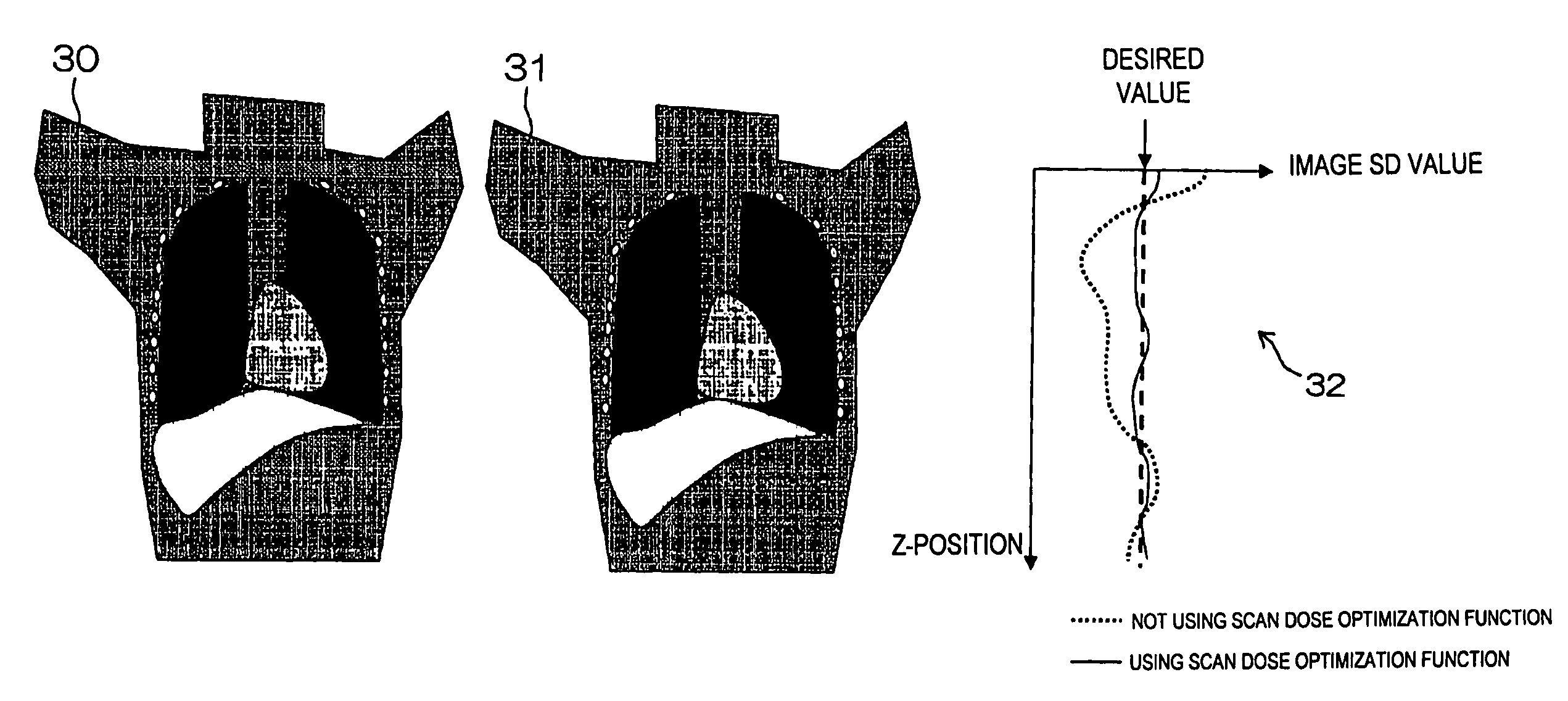
[0126]In steps S150˜S220, in the same manner as the first embodiment, the operator inputs the desired value with respect to the image quality index value (image quality SD value) (S150).

[0127]Furthermor...


PUM


Abstract

[Problems] To provide an X-ray CT apparatus capable of easily comparing image quality supposed to be obtained when not using a X-ray dose optimization function and image quality supposed to be obtained when using the X-ray dose optimization function at the stage of scan planning.[Means for Solving Problems] A 3-dimensional model of an object to be examined (17) is generated from scanogram projection data (S170). An image noise dispersion value corresponding to an imaging region of the object is predicted from the 3-dimensional model.The predicted image noise dispersion value is compared to a desired value of the image index value inputted by a user so as to calculate a modulation pattern of the irradiation X-ray amount (S200).By predicting the image quality supposed to be obtained when using and not using the X-ray dose optimization function, each of the predicted results is displayed so as to be compared on a display device (5) (S230).

Description

TECHNICAL FIELD[0001]The present invention relates to an X-ray CT apparatus, more particularly to a single slice or multi slice X-ray CT apparatus for irradiating X-ray of fan beam (sector form beam) or cone beam (conical shape or pyramid shape beam) to an object to be examined, measuring the X-ray transmitted through the object by an X-ray detector and acquiring a tomographic image of the object by back projecting the measurement data from multiple directions, which is capable of obtaining CT images with desired image quality.BACKGROUND ART[0002]A multi slice X-ray CT apparatus is generally configured, as shown in FIG. 3, to obtain projection data of an object 17 by irradiating X-ray beams of cone beam that are pyramid shape from an X-ray tube 8 and measuring X-ray after transmitting through the object by a detector 11 in which detection elements 18 are arranged two-dimensionally (in channel direction and row direction).[0003]Also in single slice X-ray CT apparatus, projection data...

Claims


Application Information

Patent Timeline
Patent Type & Authority Patents(United States)
IPC IPC(8): H05G1/44
CPCA61B6/032A61B6/542A61B6/488A61B6/463
Inventor HIROKAWA, KOICHIGOTO, TAIGA
Owner HITACHI LTD
Why Eureka
Try Eureka