
Forwardly folding tool bar

a tool bar and forward folding technology, applied in the field of forward folding tool bars, can solve the problems of insufficient flexibility, undesirable stress on certain components the substantial reduction of the working or field width of the tool bar, so as to achieve the effect of reducing manufacturing costs, durable use, and reducing manufacturing costs

Inactive Publication Date: 2009-10-20
FRIESEN ARLYN E
View PDF20 Cites 28 Cited by
  • Summary
  • Abstract
  • Description
  • Claims
  • Application Information

AI Technical Summary

Benefits of technology

[0013]Yet another object of the invention is to provide a forward folding tool bar which is flexible in its field position to accommodate rolling terrain and which is flexible in its transport position to accommodate ease of ingress and egress of fields and farmsteads having unlevel entrances.
[0019]Yet another object of the invention is to provide a tool bar having an operating width of 120 feet which, with the utilization of intermediate tongue carry wheels, results in efficiency of manufacture.
[0020]Yet another object of the invention is to provide a forward folding tool bar which is economical of manufacture, durable in use and refined in appearance.

Problems solved by technology

A major problem associated with conventional tool bars is that the working or field width thereof must be substantially reduced to enable the implement to be transported from one location to another.
In most folding tool bars of this type, the upright position of the wings is not as stable as desired and may create undesirable stress on certain components of the tool bar.
A further problem associated with the conventional folding tool bars is that they are not sufficiently flexible to compensate for irregular terrain such as in hill country, terraces, etc.
Yet another disadvantage of the prior art devices is that the wheels which support the tool bar interfere with the mounting of various attachments on the tool bar due to the location of the wheels on the tool bar.
Still another disadvantage of the conventional prior art tool bars is that they are difficult to move from the field position to the transport position and vice versa.

Method used


Image

  • Forwardly folding tool bar
  • Forwardly folding tool bar
  • Forwardly folding tool bar

Examples


Embodiment Construction

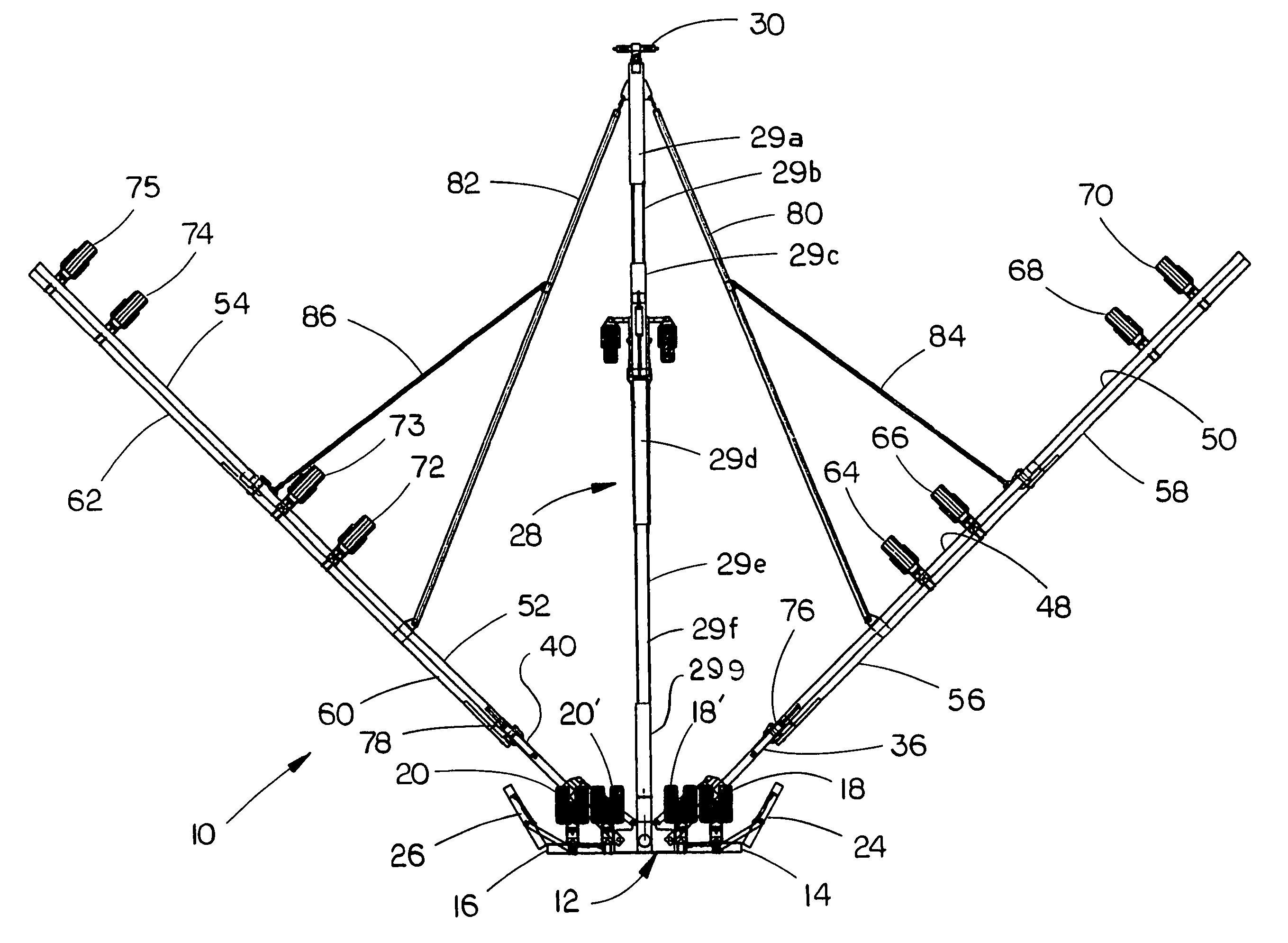
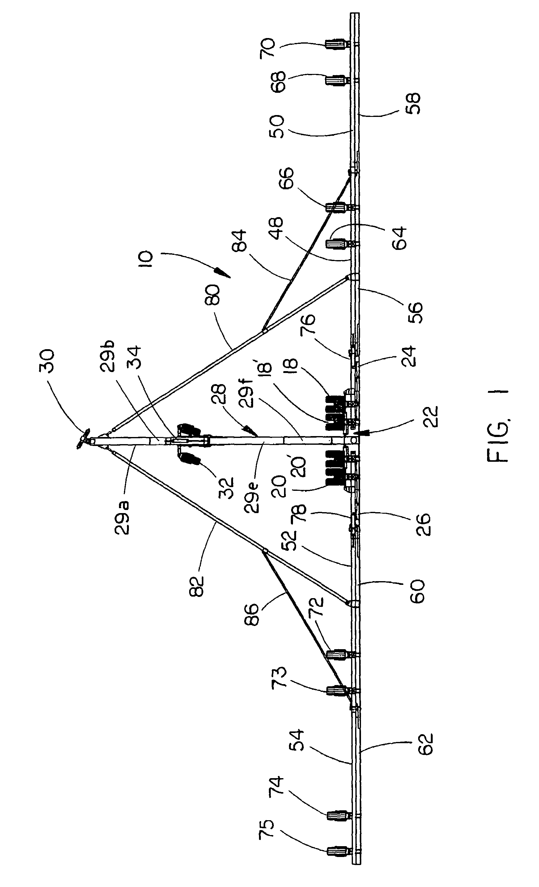
[0027]The numeral 10 refers to the forward folding tool bar of this invention. The tool bar 10 includes a center tool bar section 12 having a right end 14 and a left end 16. Preferably, center tool bar section 12 has a length of 165.0 inches and is adapted to have row units such as planters, cultivators, etc., mounted thereon in conventional fashion. Preferably, center tool bar section12 supports six rows of planters thereon which are spaced-apart at a distance of thirty inches. Four pairs of vertically movable gauge wheel assemblies 18, 18′, 20 and 20′ are secured to the center tool bar section 12 in conventional fashion for raising and lower the center tool bar section in conventional fashion. Support means 22 is secured to the center tool bar section at the center thereof and may comprise vertically spaced-apart plates such as in U.S. Pat. No. 6,702,035. A pair of wrap-around winglet tool bar sections 24 and 26 are pivotally secured to the ends 14 and 16 of center tool bar sectio...


PUM


Abstract

A forwardly folding tool bar which may be moved between field and transport positions. The tool bar includes a center tool bar section having a hinged telescopic tongue extending forwardly therefrom for connection to a tractor. Right and left wrap-around winglet tool bar sections are pivotally secured to the right and left ends of the center tool bar section and are pivotally movable between field and transport positions. Right and left wing hinges are also pivotally secured to the center tool bar section. Right and left intermediate hinge sections are pivotally secured to the outer ends of the right and left hinge sections, respectively. Right and left outer hinge sections are pivotally secured to the outer ends of the right and left intermediate hinge sections. Inner, intermediate and outer tool bar sections are secured to each of the inner, intermediate and outer hinge sections.

Description

CROSS-REFERENCE TO RELATED APPLICATION[0001]This application claims the benefit of U.S. Provisional Application Ser. No. 60 / 655,734 entitled FORWARDLY FOLDING TOOL BAR filed Feb. 24, 2005, the disclosure of which is hereby incorporated herein by reference.BACKGROUND OF THE INVENTION[0002]1. Field of the Invention[0003]This invention relates to a folding tool bar and more particularly to a forwardly folding tool bar. More particularly, the invention relates to a tool bar which has a wider operating width than any such device available on the market to date.[0004]2. Description of the Related Art[0005]Tool bars are commonly used in farming operations. The conventional tool bars normally consist of a transversely extending tool bar or frame member having a tongue or hitch secured thereto which extends forwardly therefrom for attachment to a prime mover such as a tractor. Attachments such as cultivators, planter units, stalk cutters, etc., are mounted on the tool bar to perform various ...

Claims


Application Information

Patent Timeline
IPC IPC(8): A01B49/00
CPCA01B73/065
Inventor FRIESEN, MILFORD E.
Owner FRIESEN ARLYN E
Learn More