Integrated hybrid current sensor

a current sensor and hybrid technology, applied in the direction of instruments, magnetic measurements, measurement using dc-ac conversion, etc., can solve the problems of expensive and cumbersome manufacturing of sensor arrangements

Inactive Publication Date: 2009-10-20
INFINEON TECH AUSTRIA AG
View PDF19 Cites 30 Cited by
  • Summary
  • Abstract
  • Description
  • Claims
  • Application Information

AI Technical Summary

Problems solved by technology

Such sensor arrangements are expensive and cumbersome to manufacture, so that there is a need for potential separated current sensors which on the one hand are small in their geometric dimensions and inexpensive to manufacture, and on the other hand allow for a current measurement in a very broad frequency range.

Method used


Image

  • Integrated hybrid current sensor
  • Integrated hybrid current sensor
  • Integrated hybrid current sensor

Examples


Embodiment Construction

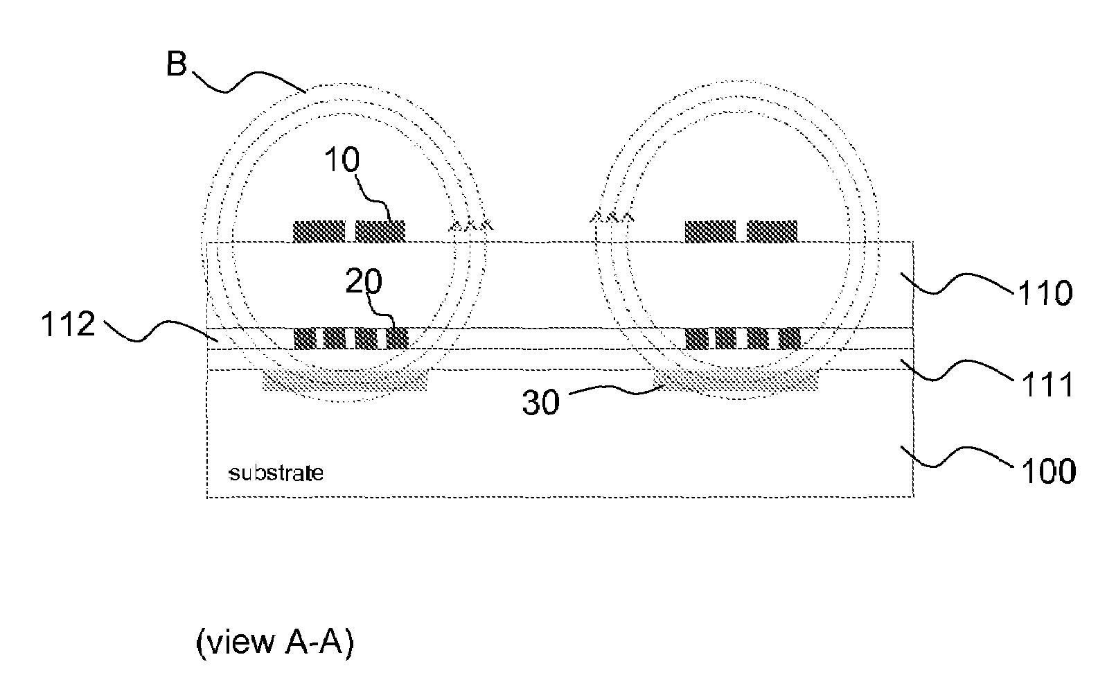
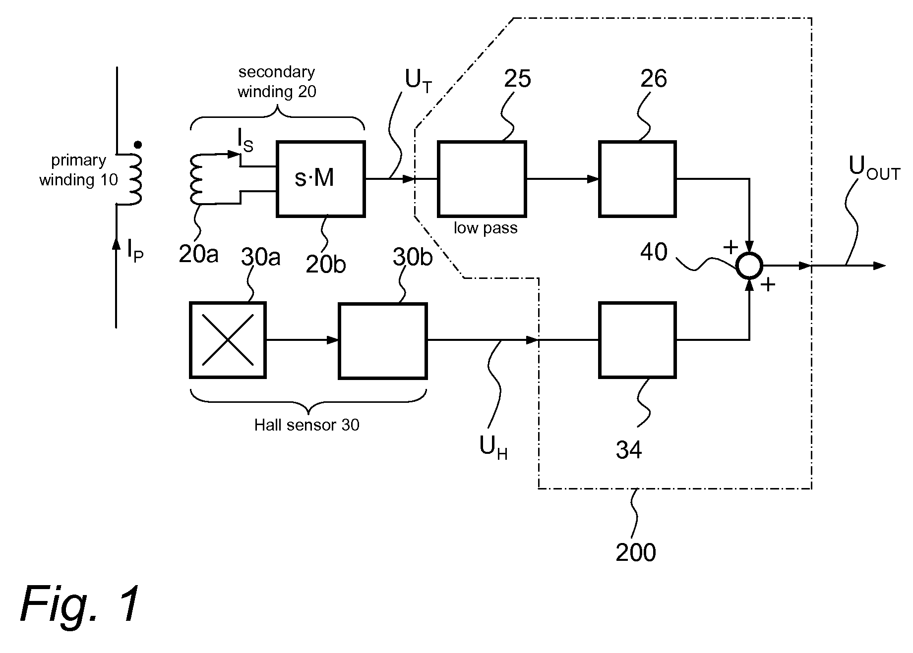
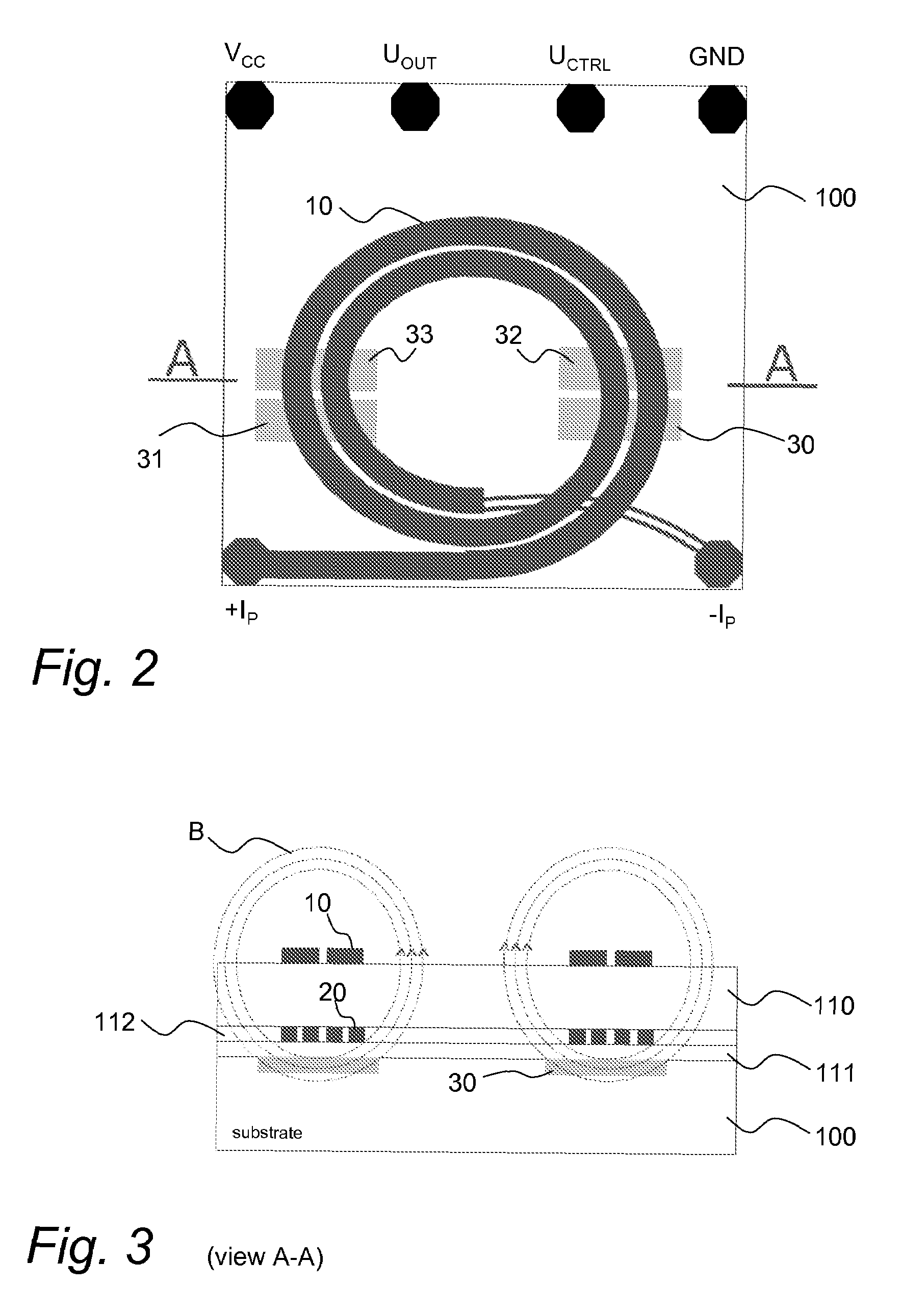
[0011]Hall sensors can achieve very good properties in terms of offset and temperature stability, if they are connected to circuits that are suitable for compensating offset and temperature drifts. However, the bandwidth of Hall elements is too low for many applications. The behavior of Hall sensors can be described approximately by a transfer function of a first-order low-pass. The combination of Hall elements with a planar transformer having planar primary and secondary windings allows for the construction of a novel current sensor, which on the one hand has the desirable DC-properties of a Hall sensor, and on the other hand has a cut of frequency much higher than common current sensors using Hall elements. Furthermore planar coreless transformer windings can be integrated on a semiconductor chip.

[0012]FIG. 1 shows a block diagram of first example of the invention. The measurement circuit depicted in FIG. 1 comprises a transformer with a primary winding 10 and a secondary winding ...


PUM


Abstract

A sensor arrangement for measuring current is disclosed. The sensor arrangement includes a substrate, at least one Hall element integrated in or arranged on the substrate, a first coil that is spaced apart from a surface of the substrate in a vertical direction, a second coil that is spaced apart in a vertical direction from the first coil, and an isolation layer that is arranged between the first coil and the second coil.

Description

TECHNICAL FIELD[0001]The invention relates to the field of integrated current sensors having a potential separation.BACKGROUND[0002]Potential separated current sensors are widespread in power electronics, medical engineering, etc. Considering multiple-purpose current sensors, it is desirable, that current can be measured in a broad frequency range including direct current (DC). Hall sensors, which are arranged in a gap of a toroidal magnetic core, are often used as current sensors in a frequency range from 0 to approximately 50 kHz. Such current sensors often require magnetic field concentrators that are arranged in a voluminous package together with the current sensor. Such sensor arrangements are expensive and cumbersome to manufacture, so that there is a need for potential separated current sensors which on the one hand are small in their geometric dimensions and inexpensive to manufacture, and on the other hand allow for a current measurement in a very broad frequency range.SUMM...

Claims


Application Information

Patent Timeline
Patent Type & Authority Patents(United States)
IPC IPC(8): G01R15/20G01R19/15
CPCG01R15/181G01R15/207G01R15/202
Inventor STRZALKOWSKI, BERNHARD
Owner INFINEON TECH AUSTRIA AG
Why Eureka
Try Eureka