
Over-360-degree-angle limit sensor device

A limit sensor and Hall sensor technology, applied in the field of limit sensors, can solve the problems of inability to measure and locate the angle of the photoelectric encoder, occupying a certain space, inconvenience of antenna installation and use, etc.

Inactive Publication Date: 2011-06-22
重庆易控科技有限责任公司
View PDF3 Cites 37 Cited by
  • Summary
  • Abstract
  • Description
  • Claims
  • Application Information

AI Technical Summary

Problems solved by technology

However, the photoelectric encoder itself has a certain volume, and it will occupy a certain space when installed in the rotary device. When the rotary device is large and has the installation space of the photoelectric encoder, the photoelectric encoder can be used for angle measurement and positioning. , but if the space of the rotary equipment itself is very small, and there is no additional space for installing the photoelectric encoder in a special environment where the size and weight are required, of course the photoelectric encoder cannot be used for angle measurement and positioning. General-purpose photoelectric encoders cannot meet their measurement requirements
[0004] Especially the main application object of the present invention is in miniaturization and light weight antenna turntable inside as the limit switch of antenna horizontal rotary motion, if do not solve measuring dead angle problem, the rotary motion direction of antenna also appears dead angle equally, so to the installation of antenna and It will cause great inconvenience to use

Method used


Image

  • Over-360-degree-angle limit sensor device
  • Over-360-degree-angle limit sensor device
  • Over-360-degree-angle limit sensor device

Examples


Embodiment example

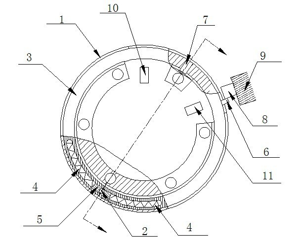
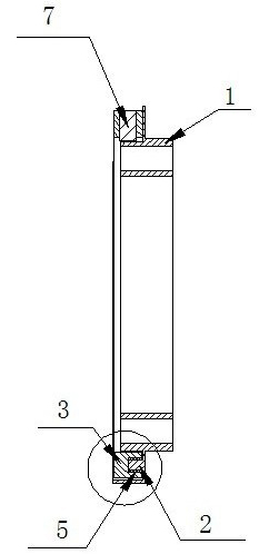
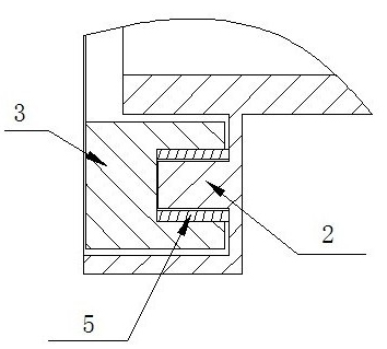
[0022] Implementation case: such as figure 1 As shown, an installation structure of a limit sensor device with an angle of more than 360° on the antenna turntable includes a support plate 1. During installation, a plurality of screws (six in the figure) are used to fix the support plate 1 to the controlled antenna deceleration On the casing of the machine, an annular rotating chute and an inner lever 2 are arranged on the support plate 1; a rotating slip ring 3 is arranged in the rotating chute in the supporting plate 1, and the rotating slide The ring 3 is set in the rotating chute and can move in the rotating chute. There is a chute on the slip ring 3. The arc length of the chute accounts for about 1 / 3 of the arc of the slip ring 3. A pair of return springs 4 are installed in the groove, and a slider 5 is set between the two return springs 4 so as to apply a force to the slider 5 along the circumferential direction of the slip ring through the inner lever 2 of the support pl...


PUM


Abstract

The invention discloses an over-360-degree-angle limit sensor device, which consists of a support disc, an inner shifting rod, a slip ring, an outer shifting rod, a return spring, a slider, a steel magnet, Hall elements and a shifting block, wherein the inner shifting rod is fixed on the support disc; the outer shifting rod is fixed on the slip ring; the return spring, the slider and the steel magnet are mounted in the slip ring; a pair of Hall elements is ranged on a measured rotor part; and the shifting block is arranged on a tested stator part. When the limit sensor device provided by invention is arranged at the limit position of the null point and the terminal point of a mechanical device with a rotary angle of 360 degrees required to be detected, the rotary angle of the mechanical device successfully reaches or exceeds 360 degrees, and the available rotary angle has no mechanical dead angle generated by the physical sizes of the sensor; and thus, the quick and accurate positioning of the mechanical devices such as the antenna turntable in the horizontal direction is guaranteed.

Description

technical field [0001] The invention relates to a limit sensor, in particular to a limit sensor device with a rotation angle exceeding 360°, and belongs to the technical field of mechanical equipment. [0002] Background technique [0003] There are angle measurement problems in many mechanical equipments that require slewing control, especially the slewing equipment that uses a semi-closed loop control system. The problem of being able to rotate within the angle range of 360°. The usual way to solve the problem is to use a general-purpose photoelectric encoder to directly connect it to the rotary body, which can basically meet the problems of angle measurement and positioning. However, the photoelectric encoder itself has a certain volume, and it will occupy a certain space when installed in the rotary device. When the rotary device is large and has the installation space of the photoelectric encoder, the photoelectric encoder can be used for angle measurement and positio...

Claims


Application Information

Patent Timeline
IPC IPC(8): G01D5/12
Inventor 朱文
Owner 重庆易控科技有限责任公司
Learn More