Sand blasting device and method for surface post-treatment of cast valve body

A sandblasting device and sandblasting technology are applied in the direction of used abrasive processing devices, explosion generating devices, spray guns, etc., which can solve the problem of difficult to meet the comprehensive sandblasting requirements of the valve body, areas that are difficult to be sandblasted, and the inner wall of the valve cannot be solved. Coverage and other issues

Pending Publication Date: 2021-06-04
JIANG SU YAN DIAN FA MEN CO LTD +1
View PDF12 Cites 0 Cited by
  • Summary
  • Abstract
  • Description
  • Claims
  • Application Information

AI Technical Summary

Problems solved by technology

[0003] The inventors found that for the elimination of residual sand on the surface and interior of the valve body after casting, and the sandblasting of the inner and outer surfaces before painting, most of the existing sandblasting methods use sandblasting nozzles located outside the valve body to perform sandblasting toward the valve body, although it can Good effect on the surface of the valve body, but for the sandblasting treatment inside the valve body, especially the sandblasting inside the small valve body, when the sand flow enters the valve body due to the angle restriction, it cannot fully cover the inner wall of th

Method used


Image

  • Sand blasting device and method for surface post-treatment of cast valve body
  • Sand blasting device and method for surface post-treatment of cast valve body
  • Sand blasting device and method for surface post-treatment of cast valve body

Examples


Embodiment 1

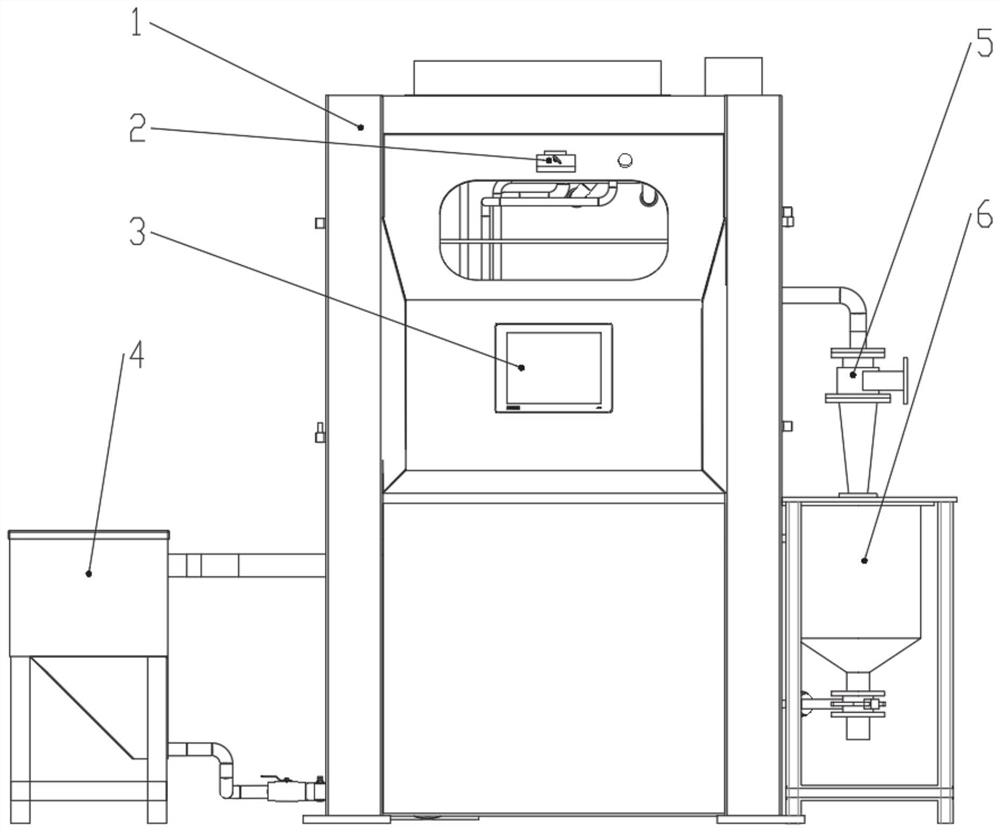
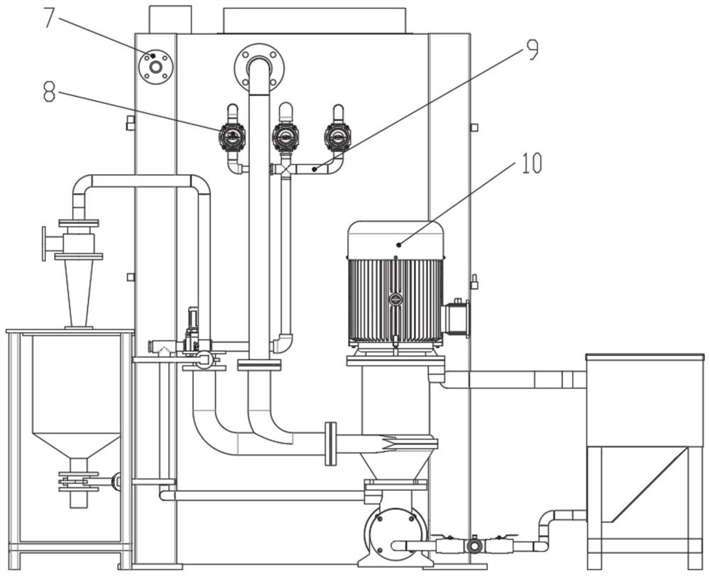
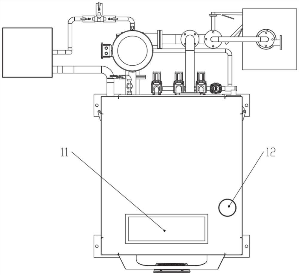
[0037] In a typical implementation of the present disclosure, such as Figure 1-Figure 7 As shown, a sandblasting device for post-treatment of the surface of a cast valve body is provided.

[0038] It includes a sandblasting mechanism, a sandblasting supply mechanism, a working cabin 1, a three-axis motion mechanism and a fixture turntable 19;

[0039] The sandblasting supply mechanism passes through the outer wall of the working cabin 1 to communicate with the sandblasting mechanism inside the working cabin 1. The three-axis motion mechanism and the fixture turntable 19 are located in the working cabin 1. The fixture turntable 19 is arranged opposite to the sandblasting mechanism. The mechanism faces the workpiece on the fixture turntable 19, and outputs sand flow to sandblast the workpiece. A reflow box 20 is provided below the turntable 19 to receive the recycled sand flow.

[0040] Based on the characteristics of the most common three-opening valve body parts (such as top...

Embodiment 2

[0068] In another typical implementation of the present disclosure, such as Figure 1-Figure 7 As shown, a sandblasting method for the post-treatment of the surface of the cast valve body is proposed, using the sandblasting device for the post-treatment of the surface of the cast valve body as described in Example 1.

[0069] Include the following steps:

[0070] Mixed blasting material:

[0071] Put the sand into the grinding liquid return tank 20 through the hatch, add water to the interior of the working cabin 1 through the water inlet pipe, and then initially mix the grinding liquid. The reflux box 20 realizes uniform mixing of water and sand.

[0072] Sandblasting:

[0073] After the sandblasting materials are mixed evenly, the abrasive liquid pump 10 starts the external circulation of the abrasive liquid. At this time, the abrasive liquid pump 10 is used to provide the feeding power, and the abrasive liquid is transported to the three sandblasting hose spray guns 13 t...


PUM


Abstract

The invention provides a sand blasting device and method for surface post-treatment of a cast valve body, and relates to the field of valve body surface treatment. The sand blasting device comprises a rotary table installed in a working cabin and provided with a clamp used for clamping a workpiece, a sand blasting mechanism comprising a plurality of sand blasting branches respectively communicated with the sand blasting supply mechanism, and a sand blasting support, wherein the output ends of the sand blasting branches are respectively connected with sand blasting nozzles; the sand blasting support is installed on a three-axis movement mechanism, the sand blasting support is provided with a plurality of cantilever rods which are arranged at included angles, and the sand blasting nozzles are installed at the tail ends of the cantilever rods in a one-to-one correspondence mode; when the rotary table and/or the three-axis movement mechanism act, the sand blasting nozzles can conduct sand blasting on the outer surface of a workpiece and/or extend into the workpiece to conduct sand blasting on the inner surface; and sand blasting is conducted on the inner surface of the workpiece, the three-axis movement mechanism drives the sand blasting support to move, the sand blasting support feeds the sand blasting nozzles at the tail ends of the cantilever rods into the workpiece to be subjected to sand blasting machining, the action range covers the inner wall of the workpiece, and the requirement for comprehensive sand blasting of the workpiece is met by combining sand blasting of the outer wall of the workpiece when the sand blasting nozzles are located outside the workpiece.

Description

technical field [0001] The disclosure relates to the field of valve body surface treatment, in particular to a sand blasting device and method for post-treatment of the surface of a cast valve body. Background technique [0002] Valves are pipeline accessories used to open and close pipelines, control flow direction, adjust and control the parameters (temperature, pressure and flow) of the conveying medium. Casting molding is the most widely used molding method in the production process of valves. Most of the casting, heat treatment and surface treatment parts must be sandblasted to remove surface scale, sticky sand, old coating, molten salt heat, rust, etc. [0003] The inventors found that for the elimination of residual sand on the surface and interior of the valve body after casting, and the sandblasting of the inner and outer surfaces before painting, most of the existing sandblasting methods use sandblasting nozzles located outside the valve body to perform sandblastin...

Claims


Application Information

Patent Timeline
IPC IPC(8): B24C1/08B24C3/08B24C3/12B24C3/32B24C5/04B24C9/00B24C5/02
CPCB24C1/086B24C3/083B24C3/12B24C3/325B24C5/04B24C9/00B24C5/02
Inventor 蔡玉奎李佳航张庆李昌跃马正平顾世军
Owner JIANG SU YAN DIAN FA MEN CO LTD
Why Eureka
Try Eureka