Localisation of vehicle or mobile objects based on embedded RFID tags

a technology of radio frequency identification and vehicle location, applied in the field of system for determining the location of vehicles, can solve the problem that the above-mentioned systems are not applicable to obtaining localization information for freely traveling vehicles

Active Publication Date: 2009-10-27
PSION TEKLOGIX
View PDF8 Cites 28 Cited by
  • Summary
  • Abstract
  • Description
  • Claims
  • Application Information

AI Technical Summary

Problems solved by technology

The above systems are however not applicable to obtaining localization information for a freely traveling vehicle.

Method used


Image

  • Localisation of vehicle or mobile objects based on embedded RFID tags
  • Localisation of vehicle or mobile objects based on embedded RFID tags
  • Localisation of vehicle or mobile objects based on embedded RFID tags

Examples


Embodiment Construction

[0016]The following description is of a preferred embodiment.

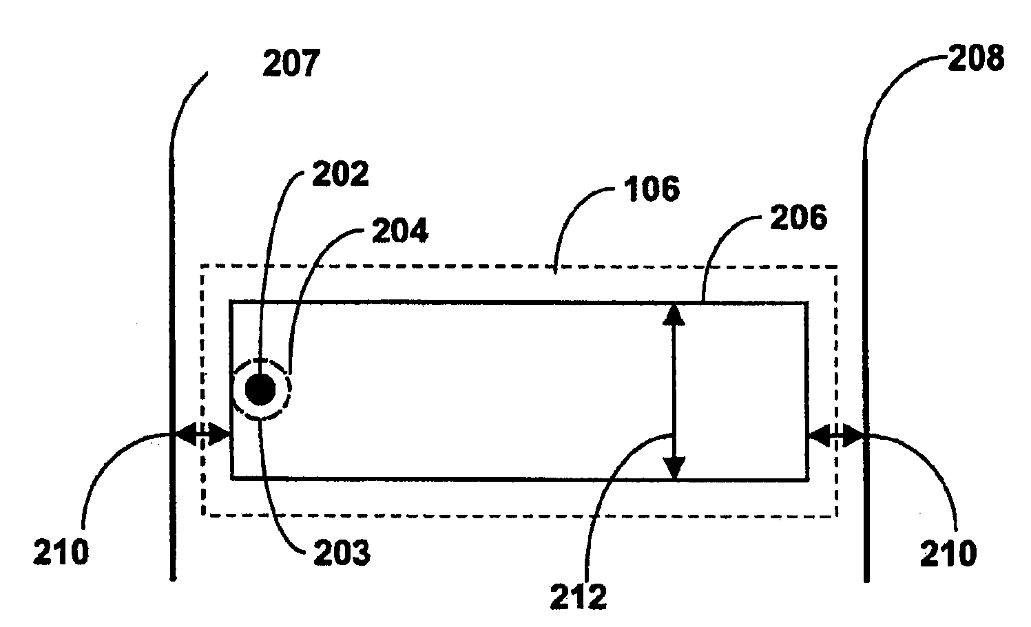
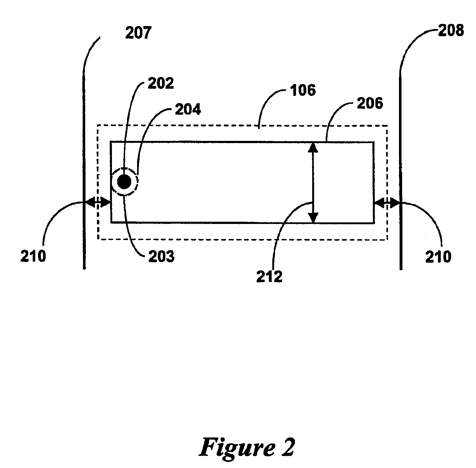
[0017]The current embodiment considers a system for determining the location of a vehicle that is moving within a warehouse environment. Within such an environment vehicles often travel in lanes where the lanes are often sized to be slightly larger than the vehicles that travel along them. A particular lane along which the vehicle travels may be either a single lane or it may be a lane amongst two or more adjacent lanes. For the case where there are two or more adjacent lanes the system must be able to differentiate between a vehicle traveling in the lane in which the system is located and one traveling in an adjacent lane. Further the vehicles will often be traveling at high speeds.

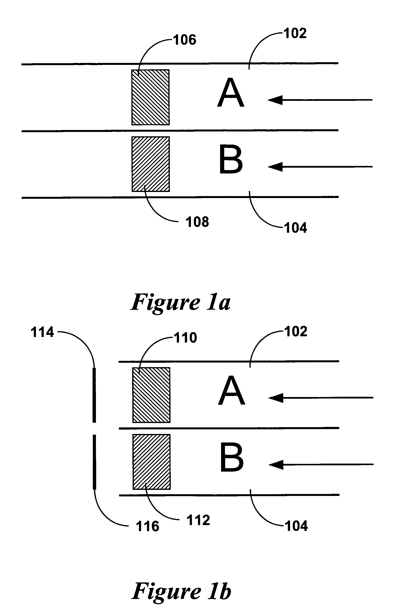
[0018]FIG. 1a is a schematic diagram of a section of two adjacent lanes i.e. lane A 102 and lane B 104, which are aligned parallel to one another for the sections shown in FIG. 1. The lanes 102 and 104 are both approximately 2 m wide. The width...


PUM


Abstract

An RFID system for determining the location of a vehicle or mobile object that passes thereover is presented. The system comprises a tag arrangement having at least one tag where the arrangement having a width of between approximately 0.5 m and 2 m.

Description

FIELD OF INVENTION[0001]The present invention generally relates to a system for determining the location of vehicles and more particularly relates to an Radio Frequency Identification (RFID) based system.BACKGROUND OF THE INVENTION[0002]RFID systems are well suited to determining the location of vehicles. In such systems the vehicle may have a tag located therein where the vehicle passes readers at particular locations or it may have a reader located therein and there are tags at fixed locations. In systems of the latter type the tags may be embedded in the surface over which the vehicle travels. Systems of the latter type are generally preferred where the vehicle is traveling within a fixed and / or enclosed area.[0003]In U.S. Pat. No. 6,049,745 a navigation system for an automatic guided vehicle is disclosed. Tags are embedded in a warehouse floor and a forklift having a reader located thereon is with use of the tags. In FIG. 1 of U.S. Pat. No. 6,049,745 tags are shown located along...

Claims


Application Information

Patent Timeline
Patent Type & Authority Patents(United States)
IPC IPC(8): G08G1/01G08B13/14G08G1/065
CPCG08G1/042E01F11/00
Inventor PORTE, PHILIPPEBONNEFOY, PIERRE
Owner PSION TEKLOGIX
Why Eureka
Try Eureka