Check patentability & draft patents in minutes with Patsnap Eureka AI!

Differential capacitive sensor and method of making same

a capacitive sensor and differential technology, applied in the field of micro electromechanical systems (mems) sensors, can solve the problems of reducing increasing the cost and package size, and affecting the accuracy of the sensor,

Inactive Publication Date: 2009-11-03
NORTH STAR INNOVATIONS
View PDF14 Cites 61 Cited by
  • Summary
  • Abstract
  • Description
  • Claims
  • Application Information

AI Technical Summary

Problems solved by technology

Two- and three-layer capacitive sensors having a teeter-totter configuration suffer from a number of drawbacks.
Unfortunately, a large proof mass requires more die area, hence increasing cost and package size.
This deformation or bending causes a non-linearity effect that results in decreased accuracy of the sensor.
For example, this nonlinearity can create DC offset in the sensor output and possibly cause dysfunction of the system in which the accelerometer is deployed.
However, the manufacture of a smaller gap and / or a thicker proof mass leads to manufacturing issues.
This configuration is inefficient in that the surface area of extended portion 42, generally termed a shield area, of movable element 30 is unused.

Method used


Image

  • Differential capacitive sensor and method of making same
  • Differential capacitive sensor and method of making same
  • Differential capacitive sensor and method of making same

Examples


Embodiment Construction

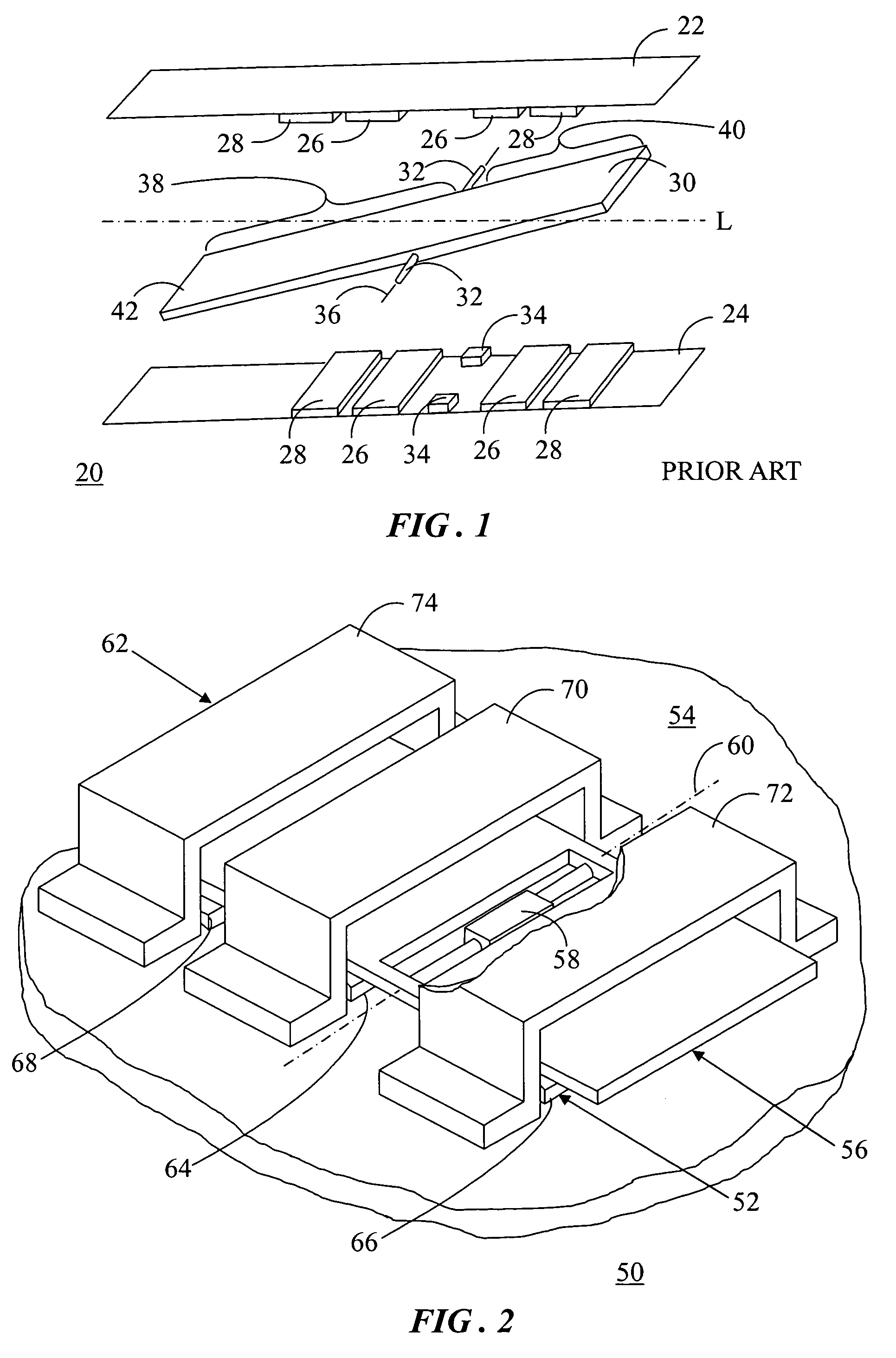
[0017]FIG. 2 shows a perspective view of a differential capacitive sensor 50 in accordance with the present invention. Sensor 50 may be, for example, a Micro Electro-Mechanical Systems (MEMS) accelerometer or other MEMS sensing device. For purposes of the following discussion, sensor 50 is referred to hereinafter as capacitive accelerometer 50. Capacitive accelerometer 50 is in a three-layer, teeter-totter configuration that provides more capacitive output than prior art devices, effectively cancels the non-linearity effect caused by non-rigid body deformation, and allows for sufficient electrostatic actuation that may be used for self test and / or for a “closed loop” or feedback design.

[0018]Capacitive accelerometer 50 includes a first static-conductive layer 52 disposed on a substrate 54. Another conductive layer, referred to herein as a movable element 56 is formed above first conductive layer 52. Movable element 56 is supported by a hinge element 58 and is allowed to pivot about ...


PUM


Abstract

A differential capacitive sensor (50) includes a movable element (56) pivotable about a rotational axis (60). The movable element (56) includes first and second sections (94, 96). The first section (94) has an extended portion (98) distal from the rotational axis (60). A static layer (52) is spaced away from a first surface (104) of the moveable element (56), and includes a first actuation electrode (74), a first sensing electrode (64), and a third sensing electrode (66). A static layer (62) is spaced away from a second surface (106) of the moveable element (56) and includes a second actuation electrode (74), a second sensing electrode (70), and a fourth sensing electrode (72). The first and second electrodes (64, 70) oppose the first section (94), the third and fourth electrodes (66, 72) oppose the second section (96), and the first and second electrodes (68, 74) oppose the extended portion (98).

Description

TECHNICAL FIELD OF THE INVENTION[0001]The present invention relates generally to micro electro-mechanical systems (MEMS) sensors. More specifically, the present invention relates to a MEMS differential capacitive accelerometer.BACKGROUND OF THE INVENTION[0002]An accelerometer is a sensor typically utilized for measuring acceleration forces. These forces may be static, like the constant force of gravity, or they can be dynamic, caused by moving or vibrating the accelerometer. An accelerometer may sense acceleration or other phenomena along one, two, or three axes or directions. From this information, the movement or orientation of the device in which the accelerometer is installed can be ascertained. Accelerometers are used in inertial guidance systems, in airbag deployment systems in vehicles, in protection systems for a variety of devices, and many other scientific and engineering systems.[0003]Capacitive-sensing MEMS accelerometer designs are highly desirable for operation in high...

Claims


Application Information

Patent Timeline
Patent Type & Authority Patents(United States)
IPC IPC(8): G01P15/125
CPCG01P15/125G01P2015/0831
Inventor MCNEIL, ANDREW C.LIN, YIZHENMILLER, TODD F.
Owner NORTH STAR INNOVATIONS
Features
  • R&D
  • Intellectual Property
  • Life Sciences
  • Materials
  • Tech Scout
  • Unparalleled Data Quality
  • Higher Quality Content
  • 60% Fewer Hallucinations
Learn More