
Positioning correction system and method for single and multi-channel ground penetrating radar

a correction system and ground penetrating radar technology, applied in the field of subsurface evaluation and object detection, to achieve the effect of improving accuracy

Inactive Publication Date: 2009-11-03
UNDERGROUND IMAGING TECH
View PDF12 Cites 17 Cited by
  • Summary
  • Abstract
  • Description
  • Claims
  • Application Information

AI Technical Summary

Benefits of technology

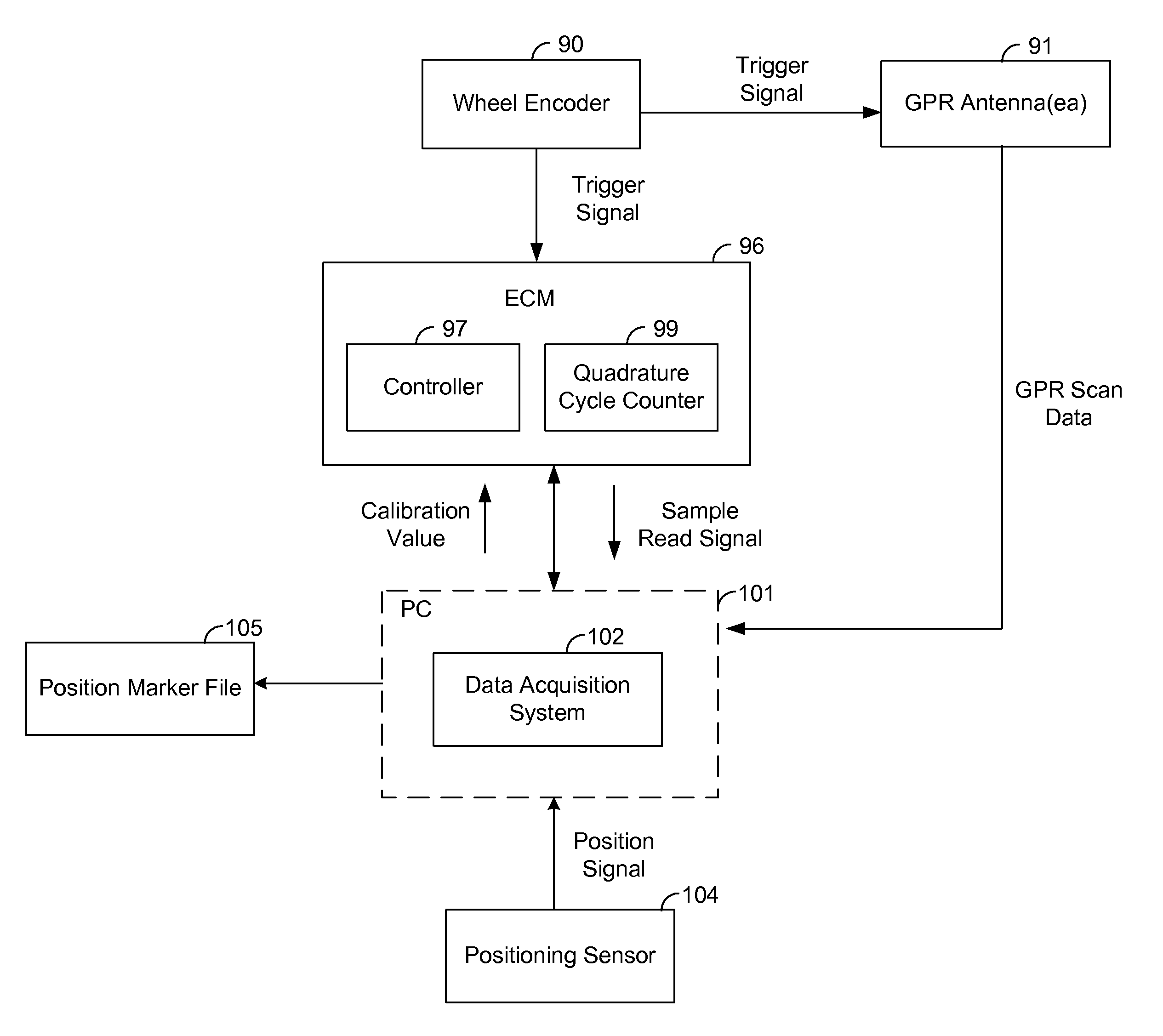
"The present invention relates to systems and methods for accurately sensing and positioning underground utilizing a mobile ground penetrating radar (GPR) system and a mobile geophysical instrument. The invention addresses the problem of variable time delays between the collection of GPR scan data and the recording of position data, which can result in a delay of up to several seconds between the time when the GPR data is collected and the time when the position data is recorded. The invention proposes a system and method that uses a distance transducer to produce trigger signals and a position sensor to capture GPR scan data and position data, which is then associated with each other to eliminate the variable time delay. The invention also includes a module that can be attached to a GPR system and a method for computing the position of the GPR instrument while it is in motion. Overall, the invention improves the accuracy and efficiency of subsurface sensing and positioning."

Problems solved by technology

A variable time delay results between a time when the GPR scan data is collected and a time when the position data associated with the GPR scan data is recorded.
A variable time delay results between a time when data for each geophysical data set is collected by the processor and a time when a position associated with each geophysical data set is recorded by the processor.

Method used


Image

  • Positioning correction system and method for single and multi-channel ground penetrating radar
  • Positioning correction system and method for single and multi-channel ground penetrating radar
  • Positioning correction system and method for single and multi-channel ground penetrating radar

Examples


Embodiment Construction

[0026]In the following description of the illustrated embodiments, references are made to the accompanying drawings forming a part hereof, and in which are shown by way of illustration, various embodiments by which the invention may be practiced. It is to be understood that other embodiments may be utilized, and structural and functional changes may be made without departing from the scope of the present invention.

[0027]Systems, devices or methods according to the present invention may include one or more of the features, structures, methods, or combinations thereof described herein. For example, a device or system may be implemented to include one or more of the advantageous features and / or processes described below. It is intended that such a device or system need not include all of the features described herein, but may be implemented to include selected features that provide for useful structures, systems, and / or functionality.

[0028]The description of the methods and systems pro...


PUM


Abstract

A mobile geophysical instrument produces geophysical data sets each associated with a position computed by use of a position sensor. A variable time delay results between a time when data for each geophysical data set is collected and a time when a position associated with each geophysical data set is recorded. A module receives distance transducer data and includes circuitry configured to generate a module signal based on trigger signals from the distance transducer and a calibration value. A data acquisition system (DAS) receives geophysical data sets from the geophysical instrument, positioning data from the positioning sensor, and the module signals. The DAS generates a DAS timestamp in response to each module signal and associates the DAS timestamp with each geophysical data set and a position associated with the geophysical data set, so as to substantially eliminate the variable time delay.

Description

RELATED APPLICATIONS[0001]This application claims the benefit of Provisional Patent Application Ser. No. 61 / 001,030 filed on Oct. 30, 2007, to which priority is claimed pursuant to 35 U.S.C. §119(e) and which is hereby incorporated herein by reference in its entirety.FIELD OF THE DISCLOSURE[0002]The present disclosure relates generally to the field of subsurface evaluation and object detection, and, more particularly, to systems and methods for improving the positional accuracy of geophysical and geologic data, such as ground penetrating radar (GPR) data for single and multiple channel GPR systems.BACKGROUND[0003]Various techniques have been developed to detect and locate underground utilities and other manmade or natural subsurface structures. It is well understood that before trenching, boring, or otherwise engaging in invasive subsurface activity to install or access utilities, it is imperative to know the location of any existing utilities and / or obstructions in order to assist ...

Claims


Application Information

Patent Timeline
Patent Type & Authority Patents(United States)
IPC IPC(8): G01S13/88G01V3/12G01S19/05
CPCG01V3/12G01S13/885
Inventor RYERSON, KENNETH J.SJOSTROM, KEITHHANSON
Owner UNDERGROUND IMAGING TECH
Learn More