
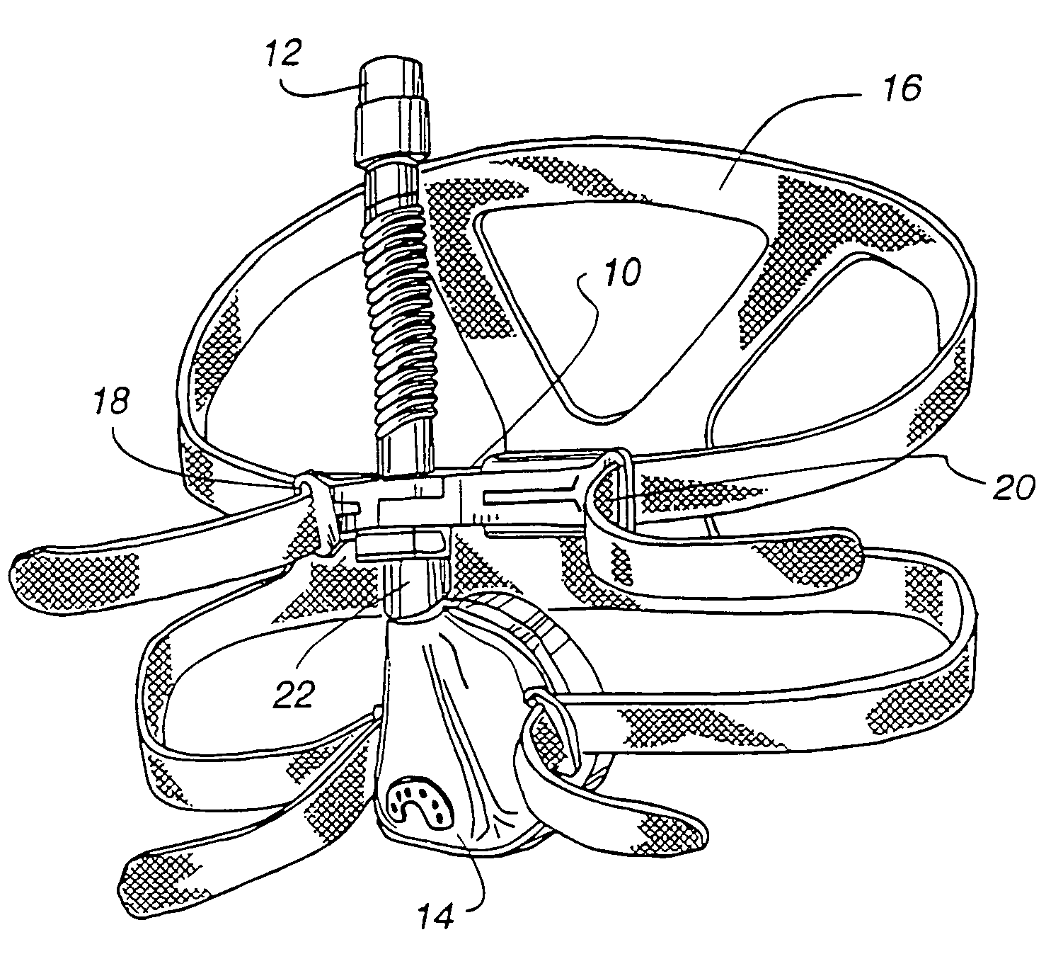
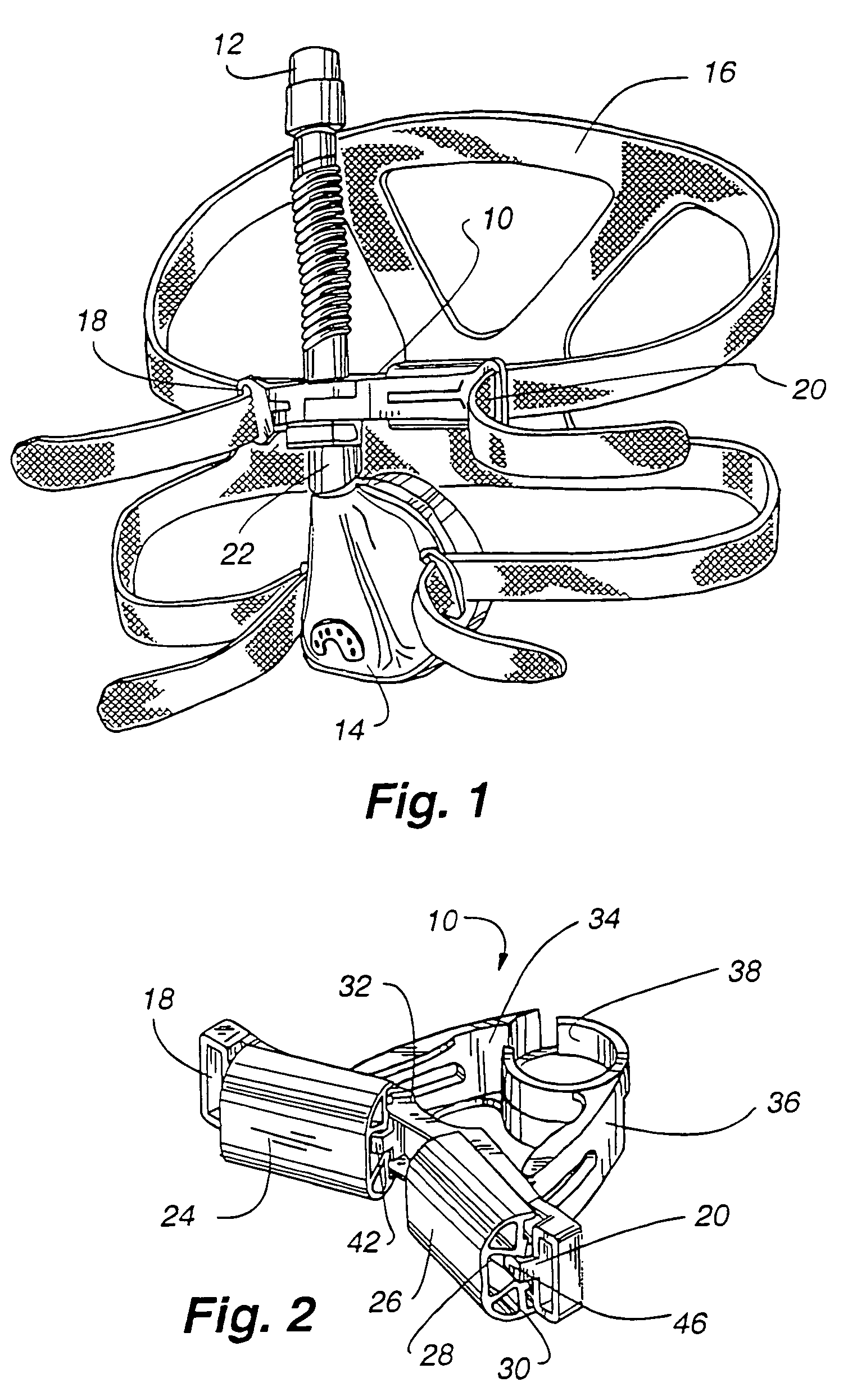
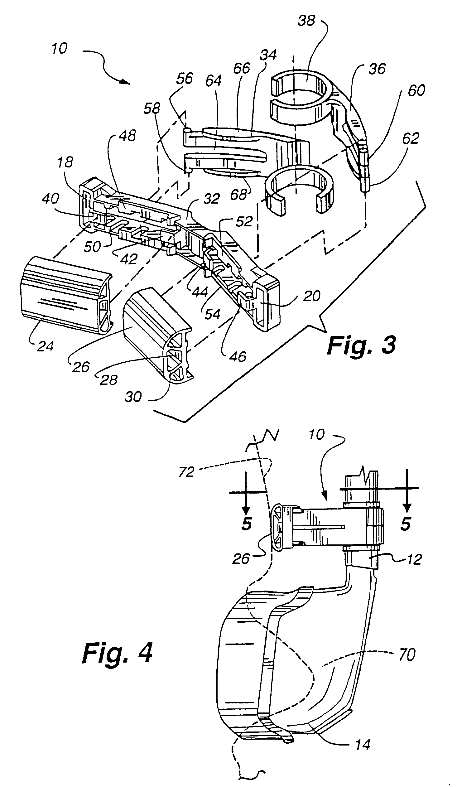
Forehead support for facial mask

a head support and mask technology, applied in the direction of breathing masks, breathing protection, inhalators, etc., can solve the problems of unduly hard pressure on the wearer's nose, mask movement on the wearer's face, wearer's inability to see where to place his or her fingers, etc., to achieve the effect of maintaining the necessary strength, easy compression, and convenient assembly

Inactive Publication Date: 2009-11-10
RESMED LTD
View PDF20 Cites 61 Cited by
  • Summary
  • Abstract
  • Description
  • Claims
  • Application Information

AI Technical Summary

Benefits of technology

[0017]The present invention is directed to an improved version of the type of forehead support discussed above. In particular, the present invention utilizes improved arms extending from the mask or gas supply line for adjustably engaging the bridge for allowing positioning of the mask on the face. First, extending portions of the arms are redesigned to compress more easily than the extending portions of the related art arms discussed above while at the same time maintaining the strength necessary for adequately supporting the airflow tube. Thus, the engaging pins may more easily be compressed together to allow for adjustment of the arms with respect to the bridge.
[0018]Furthermore, the extending portions of the arms are provided with locking portions that maintain alignment of the pins with respect to one another as they are being compressed to prevent lateral deflection of the pins, unintended stress loading on the arms and to allow easier engagement of the pins with the slots upon release of the extending portions.
[0019]Finally, arc portions of the arms that come into contact with the airflow tube 12 are undercut and radiused to prevent sticking or binding of the arms as they are pivoted about the airflow tube during adjustment of the forehead support, as compared to the related arm embodiment. Thus, the arms more easily pivot about the airflow tube during adjustment of the forehead support.
[0020]These improvements make it easier to adjust the forehead support, as well as make it easier to disassemble the arms from the bridge to allow thorough cleaning of the bridge and other support components.

Problems solved by technology

One of the problems that arises with the use of the mask is that in order for the straps to be tight, the mask is compressed against the wearer's face and may push unduly hard on the wearer's nose.
Additionally, the mask may move around on the wearer's face.
This is especially important when the mask and forehead support are positioned on the wearer's head because at such time, the wearer cannot easily see where to place his or her fingers to adjust the forehead support.

Method used


Image

  • Forehead support for facial mask
  • Forehead support for facial mask
  • Forehead support for facial mask

Examples


Embodiment Construction

[0041]FIG. 14 shows a top view of an improved embodiment of an arm for use with the present invention. Arm 200 includes a semicircular portion 202 and an extending portion 204 attached thereto. Semicircular portion 202 includes two arc portions 230 and 232 and an inner bore 234. The two arc portions 230 and 232 are both recessed or undercut near their ends, as shown by the phantom lines 236 and 238. Thus, the inner bore 234 is not perfectly circular in shape near the ends of arc portions 230 and 232. Ends 240 and 242 of the arc portions 230 and 232, respectively, are well radiused to prevent binding of the arm on the airflow tube during pivoting.

[0042]Extending portion 204 includes two flange portions 206 and 208 on which generally oval depressions 210 and 212 are respectively positioned. Bridge engagement pins 214 and 216 are positioned at far ends of flange portions 206 and 208, respectively, and project, respectively, upwardly and downwardly from the arm 200. A space 218 separate...


PUM


Abstract

The present invention discloses an adjustable forehead support for a nasal or full-face mask wherein the forehead support may be adjusted for the different shapes and sizes of a facial profile. The forehead support utilizes a dual-arm system that adjusts the position of the forehead support vis-á-vis the mask and / or airflow tube. The angle of the mask to the face may be adjusted with the present invention.

Description

[0001]This application is a continuation of application Ser. No. 10 / 685,001, filed Oct. 15, 2003, now U.S. Pat. No. 6,918,390, which is a continuation of application Ser. No. 09 / 935,778, filed Aug. 24, 2001, now U.S. Pat. No. 6,679,261, which claims the benefit of U.S. Provisional Application No. 60 / 227,472, filed Aug. 24, 2000, each incorporated herein by reference in its entirety.BACKGROUND OF THE INVENTION[0002]1. Field of the Invention[0003]The present invention generally relates to an improved comfort device to be used with a nasal mask. In particular, the device is useful in combination with masks which are used for the treatment of respiratory conditions and assisted respiration. The invention assists in fitting the mask to the face as well.[0004]2. General Background[0005]Nasal masks are commonly used in the treatment of respiratory conditions and sleep disorders by delivering a flow of breathable gas to a patient to either assist the patient in respiration or to provide a t...

Claims


Application Information

Patent Timeline
Patent Type & Authority Patents(United States)
IPC IPC(8): A61M11/00A61M16/06
CPCA61M16/06A61M16/0633A61M16/0683A61M16/065A61M16/0655
Inventor LITHGOW, PERRY DAVIDSTYLES, ROBERT EDWARDZIOLKOWSKI, ZDZISLAW ANTONIKWOK, PHILIP RODNEY
Owner RESMED LTD
Learn More