Packer cup

a technology of packaging cups and troughs, which is applied in the field of packaging cups, can solve the problems of device failure, high cost of opening pipes or tubes, and often wear of outer coverings, and achieve the effect of fast wear and tear

Inactive Publication Date: 2011-06-14
ASSOCD RES DEV
View PDF25 Cites 8 Cited by
  • Summary
  • Abstract
  • Description
  • Claims
  • Application Information

AI Technical Summary

Benefits of technology

[0012]Furthermore, the utilization of this softer material along a longer length of the cup would allow the cup to compress more easily which would be easier on the equipment and less prone to catch on the collars of the equipment. The casings would generally have a collar resulting in a groove upon which the harder material of the packing cup would jam. Consequently, the use of a packing cup having a longer length of softer material would prevent the cups from jamming on the collar grooves.
[0013]In addition, because of the larger area of contact between the softer and harder materials there is less likelihood of separation of the two materials.
[0014]Finally, the larger area of the soft material of the packing cup would provide a better seal.

Problems solved by technology

During use, the outer covering will often wear away exposing the metal reinforcement.
In that case, it can be extremely expensive to open the pipe or tube, to retrieve the cup.
It is described that the juncture between the two elastomers is a fault line and typically such a device fails along this line sooner than with other types of seals.
Additionally, the interface between the softer material and harder material is prone to separation in some circumstances.

Method used


Image

  • Packer cup
  • Packer cup
  • Packer cup

Examples


first embodiment

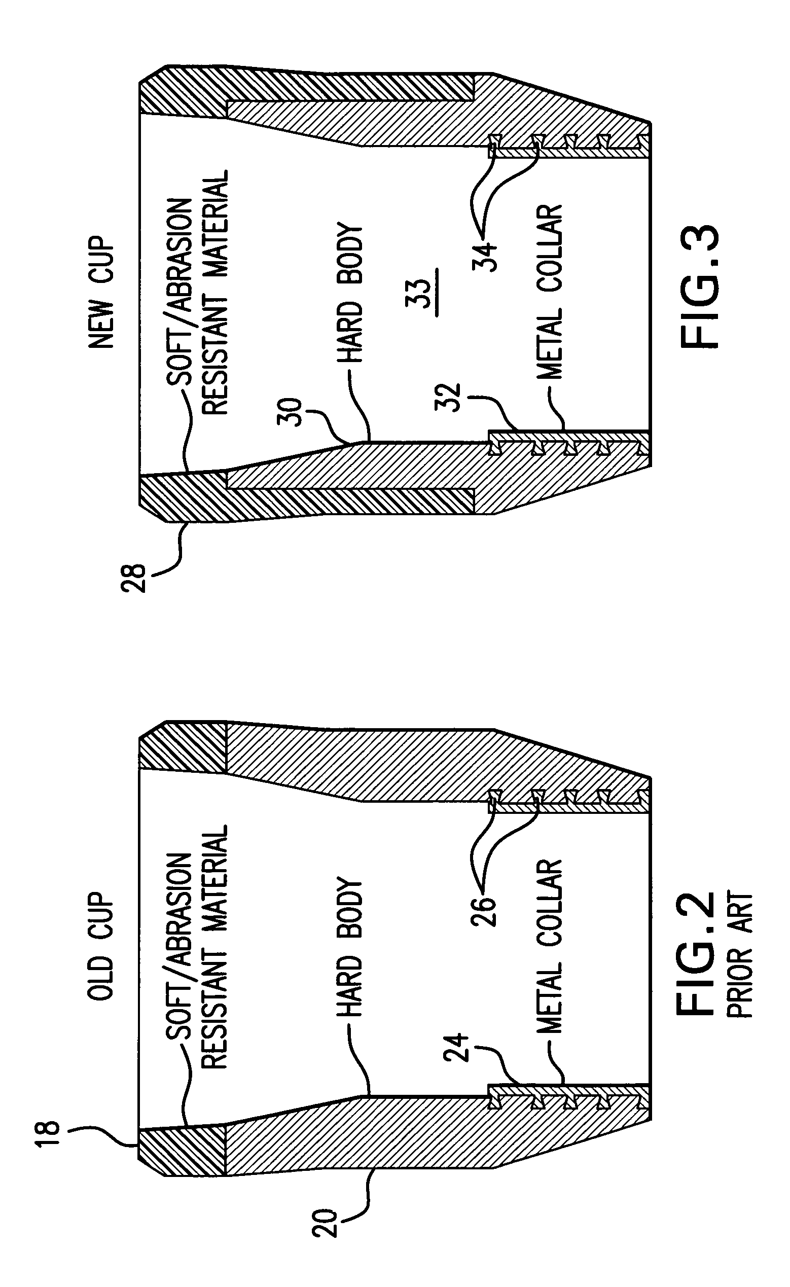
[0030]the packing cup of the present invention is illustrated with respect to FIG. 3. A soft / abrasion resistant material 28 similar with respect to the density and hardness of the soft / abrasion resistant material 18 would be provided in the bell-shaped end as well as extend for at least one third the length of the improved packer cup. The length of the cup could vary between three and six inches. Therefore, if the blank for the packer cup was 4.0″, the soft / abrasion resistant material 28 would extend for at least 1.33″ or, could extend for most of the entire length of the packer cup. Similar to the prior art packer cup, the packer cup of the present invention could include a collar 32 positively attached to the hard / rigid material 30 by adhesion of the two materials, mechanically by interlocking the materials together, or by the use of any other suitable means, such as an adhesive. Similarly, the collar 32 could include a plurality of fingers 34 inserted into various apertures in th...

second embodiment

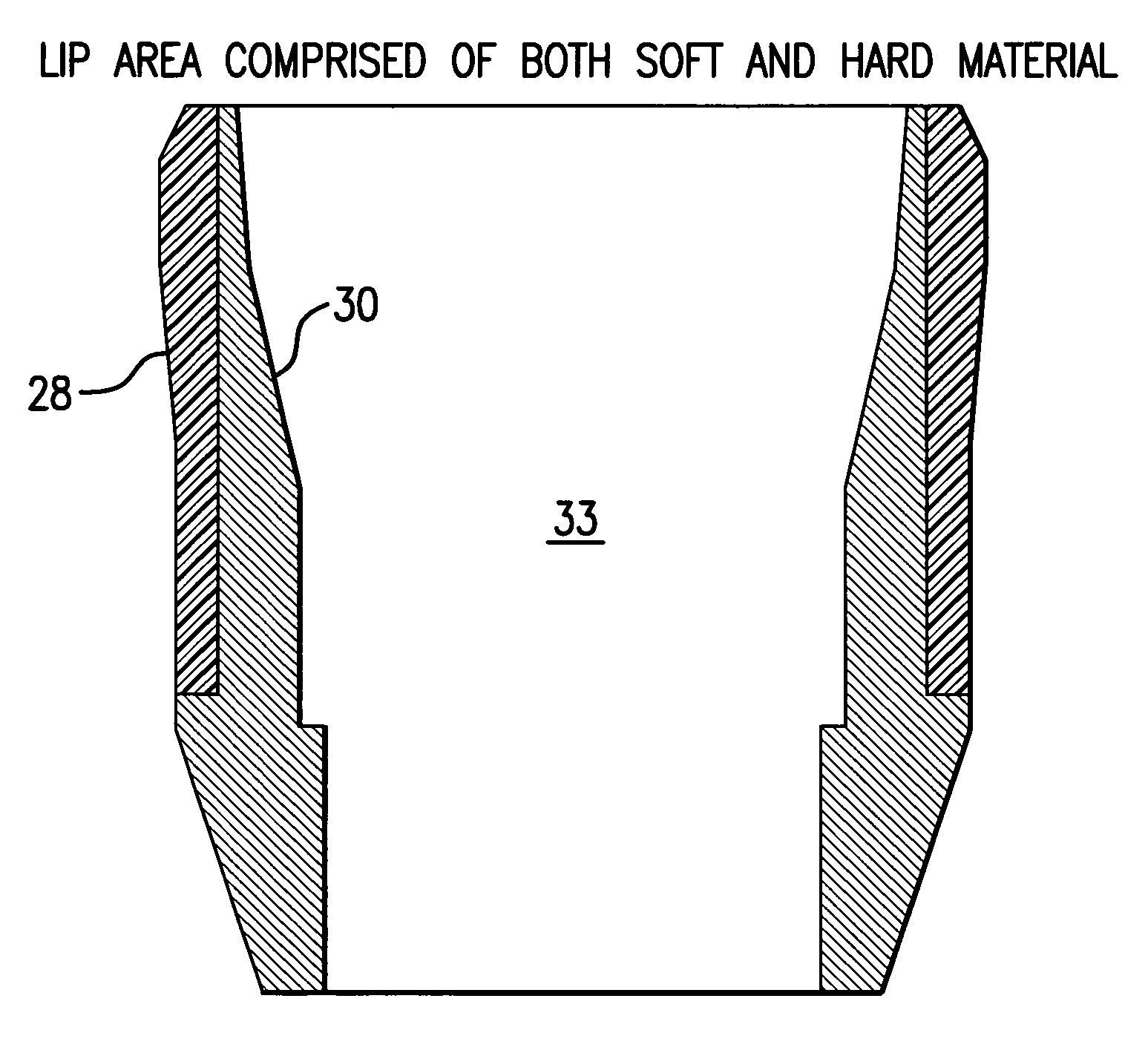
[0035]FIG. 11 illustrates the present invention wherein the lip area includes both the softer material 28 as well as the harder material 30. In this embodiment, the inner surface of the sleeve 33 would only be constructed from the harder elastomer material.

[0036]Similar to the Plomp patent, the packer cup of the present invention could exhibit the same relationship of density and hardness of the softer material to the harder material. Therefore, the softer material 28 could have a density of approximately 1.07 and hardness of approximately 80-95 SHORE A, and the harder material 30 would have a density of approximately 1.3 and a hardness of approximately 60 SHORE D. However, it is noted that other parameters could be employed as long as the material 28 was softer than the material 31.

[0037]FIG. 12 describes the utilization of a cup retainer 56 when it is placed in the mold during a first shot as described with respect to FIG. 6. Generally, cup retainers are typically metal and serve ...


PUM


Abstract

A packer cup for sealing the interior of a pipe under pressure includes a first region of relatively soft material and a second region of relatively hard material. The region of the relatively softer material would begin at the lip of the cup and extend for at least one third the length of the cup up to the entire length of the cup.

Description

FIELD OF THE INVENTION[0001]The present invention is directed to a device for sealing the interior of a casing or pipe allowing pressure to be applied in the sealed off section of the casing. The present invention is used to seal formations when servicing wells or to pressure test tubing or piping.BACKGROUND OF THE INVENTION[0002]The present invention is an improvement over U.S. Pat. No. 7,261,153, issued to Plomp. Both the present invention as well as the Plomp patent are assigned to the same assignee and the Plomp patent is incorporated by reference.[0003]It is known in the art to provide a bell-shaped resilient member to use as a seal to seal off a section of pipe so that the section can be tested with pressure. Such seals are normally constructed from reinforced elastomer and dimensioned so that when pressure is applied to the sealed off portion, the pressure causes the bell-shaped member to expand against the inner wall of the pipe and seal it. A mandrel is often used with such...

Claims


Application Information

Patent Timeline
Patent Type & Authority Patents(United States)
IPC IPC(8): E21B33/126
CPCE21B33/126
Inventor TEMPLETON, MATTHEWTEMPLETON, BRIAN
Owner ASSOCD RES DEV
Why Eureka
Try Eureka