Process of forming a capacitative audio transducer

a capacitive, allsilicon technology, applied in the direction of variable capacitors, decorative arts, chemical vapor deposition coatings, etc., can solve the problems of incompatibility with high-volume processes, long process steps for fabricating all-silicon microphones of the type disclosed by bernstein and aigner et al., and the plastic deformation of surrounding structures is easy to be induced by process deformation,

Inactive Publication Date: 2006-11-14
DELPHI TECH IP LTD
View PDF14 Cites 14 Cited by
  • Summary
  • Abstract
  • Description
  • Claims
  • Application Information

AI Technical Summary

Benefits of technology

[0011]From the above, it can be appreciated that the present invention provides an audio transducer characterized by an uncomplicated fabrication process, which can be readily modified to promote both performance and processing characteristics of the transducer. The single-crystal silicon layers that define the first and second capacitor plates are preferably doped to be low stress, and are less prone to process-induced deformation and package-induced stresses than the corresponding structures of prior art all-silicon monolithic audio transducers. Because the single-crystal silicon layers are not deposited films requiring high processing temperatures, the surrounding structures are also less vulnerable to plastic deformation. Another advantage of the invention is that the distance between the capacitive plates is established by the thicknesses of etched layers as a result of the wafer bonding process, enabling the capacitive gap to be precisely predetermined.
[0012]Other objects and advantages of this invention will be better appreciated from the following detailed description.

Problems solved by technology

Processes for fabricating all-silicon microphones of the type disclosed by Bernstein and Aigner et al. are typically long, cumbersome, expensive, and not compatible with high-volume processes.
In addition, the silicon sensing membranes can be prone to process-induced deformation and package-induced stresses that can prevent or interfere with proper operation of the device.
As well known in the art, stresses in deposited films such as the silicon sensing membrane of Aigner et al. are difficult to control, and high temperature steps required to form and process the stationary membrane of Aigner et al. can lead to plastic deformation of surrounding structures, including the silicon sensing membrane.
A further disadvantage of capacitive audio devices such as those taught by Bernstein and Aigner et al. is the difficulty with which the distance between the capacitively coupled membranes can be precisely predetermined.

Method used


Image

  • Process of forming a capacitative audio transducer
  • Process of forming a capacitative audio transducer
  • Process of forming a capacitative audio transducer

Examples


Embodiment Construction

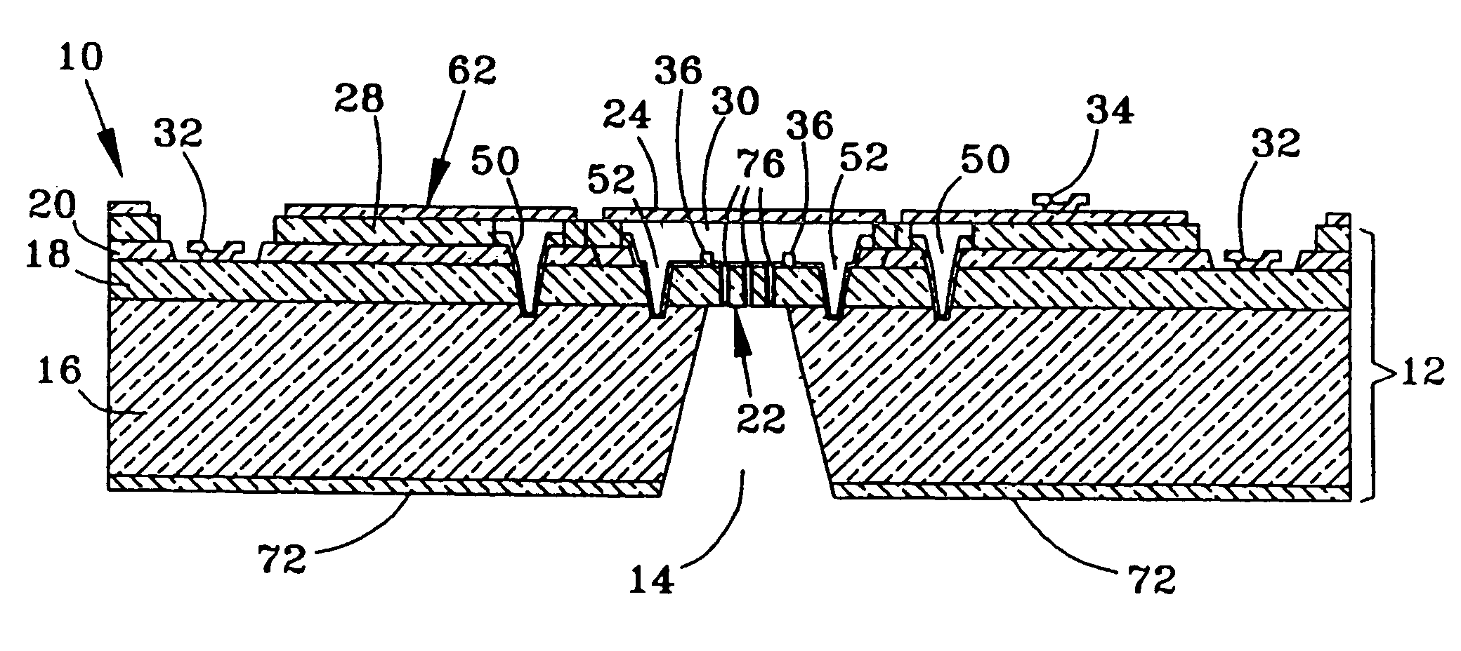
[0016]FIG. 14 represents an all-silicon monolithic capacitive-coupled condenser microphone 10 of a type produced by the process of the present invention. As illustrated, the microphone 10 includes a base wafer, referred to as a handle wafer 12, in which a backside cavity 14 has been etched. The handle wafer 12 includes a silicon substrate 16, a doped first epitaxial layer 18, a second epitaxial layer 20, and an insulating film, referred to herein as a bond oxide layer 28, on the epitaxial layer 20. The first epitaxial layer 18 defines a fixed capacitor plate 22 that is spaced apart by a gap 30 from a movable capacitor plate 24, which is defined by a layer 62 of doped single-crystal silicon. The movable capacitor plate 24 is responsive to sound waves relative to the fixed capacitor plate 22. The fixed and movable capacitor plates 22 and 24 are both doped to be electrically conductive, and as a result of being capacitively coupled (as will be discussed below) form the capacitive sensi...


PUM

PropertyMeasurementUnit
thicknessaaaaaaaaaa
thicknessaaaaaaaaaa
thicknessaaaaaaaaaa

Abstract

A process of forming a capacitive audio transducer, preferably having an all-silicon monolithic construction that includes capacitive plates defined by doped single-crystal silicon layers. The capacitive plates are defined by etching the single-crystal silicon layers, and the capacitive gap therebetween is accurately established by wafer bonding, yielding a transducer that can be produced by high-volume manufacturing practices.

Description

CROSS REFERENCE TO RELATED APPLICATIONS[0001]The present application is a continuation application of U.S. application Ser. No. 10 / 231,325 filed on Aug. 29, 2002 now U.S. Pat. No. 6,829,814.STATEMENT REGARDING FEDERALLY SPONSORED RESEARCH[0002]Not applicable.BACKGROUND OF THE INVENTION[0003](1) Field of the Invention[0004]The present invention generally relates to semiconductor micromachined devices. More particularly, this invention relates to a process of making an all-silicon capacitive microphone, in which a membrane used to sense sound vibration is formed of substantially stress-free single-crystal silicon bonded to a support substrate.[0005](2) Description of the Related Art[0006]There is a continuing desire for audio devices that are smaller in size, lower in cost, and can be manufactured using high-volume manufacturing practices, yet are characterized by high reliability and sensitivity. An example is acoustic transducers such as microphones that make use of a silicon sensin...

Claims


Application Information

Patent Timeline
Patent Type & Authority Patents(United States)
IPC IPC(8): H04R31/00H01L21/00B81C1/00H04R19/00H04R25/00
CPCB81C1/00666H04R19/005H04R31/00B81B2201/0257B81B2203/0127Y10T29/43H04R31/006Y10T29/435Y10T29/49005
Inventor FREEMAN, JOHN E.BANEY, WILLIAM J.BETZNER, TIMOTHY M.CHILCOTT, DAN W.CHRISTENSON, JOHN C.VAS, TIMOTHY A.QUEEN, GEORGE MLONG, STEPHEN P
Owner DELPHI TECH IP LTD
Why Eureka
Try Eureka