Dispensing applicator for fluids

a technology for fluids and applicators, applied in the direction of ink reservoir pens, other medical devices, coatings, etc., can solve the problems of patient discomfort, chemical burns, electrical shock, and even electrical shock, and achieve the effect of reducing the number of users

Inactive Publication Date: 2009-11-10
BIOMED PACKAGING SYST
View PDF13 Cites 58 Cited by
  • Summary
  • Abstract
  • Description
  • Claims
  • Application Information

AI Technical Summary

Problems solved by technology

Prior dispensing applicators allow excess amount fluid to flow too quickly, and the fluid tends to pool on the surface.
Depending upon the fluid being dispensed, such pooling can lead to patient discomfort, chemical burns, and even electrical shock if the dispensed fluid comes into contact with electrical leads attached to the patient's body.
As the volume of the dispensed fluid gradually increases at the rear portion of the absorbent member, the fluid starts uncontrollably dripping, thus, causing substantial inconvenience to a user.

Method used


Image

  • Dispensing applicator for fluids
  • Dispensing applicator for fluids
  • Dispensing applicator for fluids

Examples


Embodiment Construction

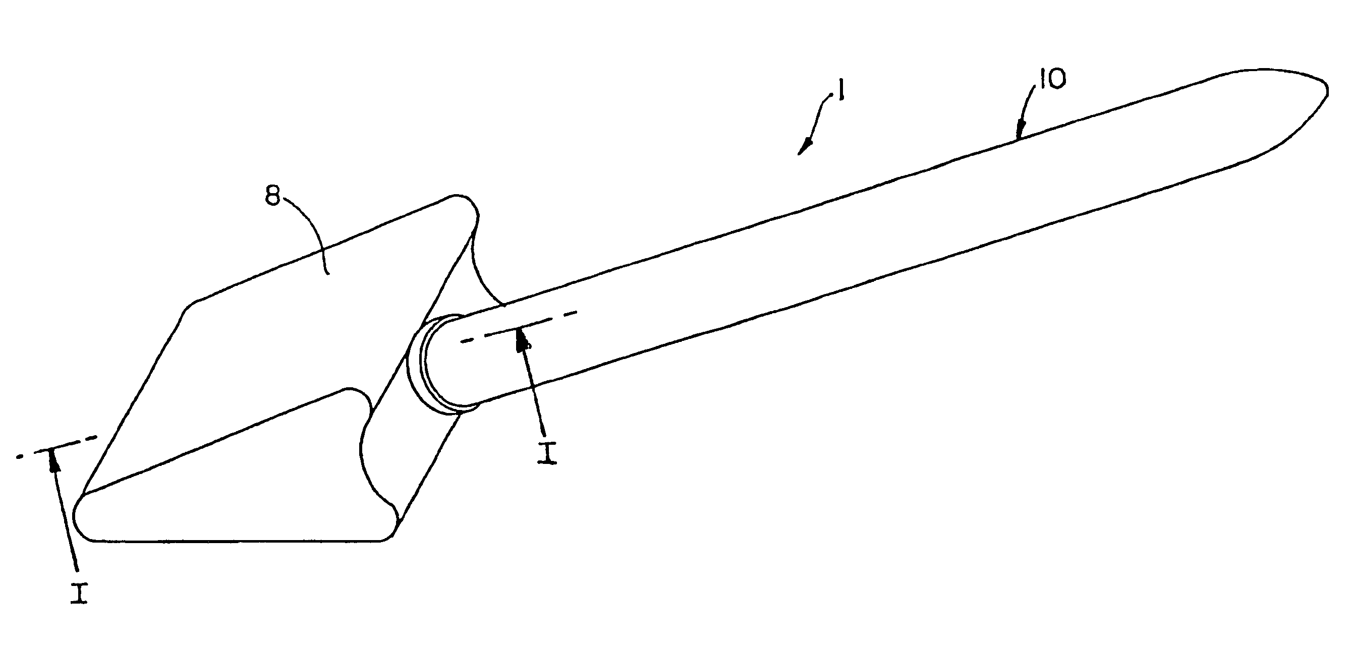
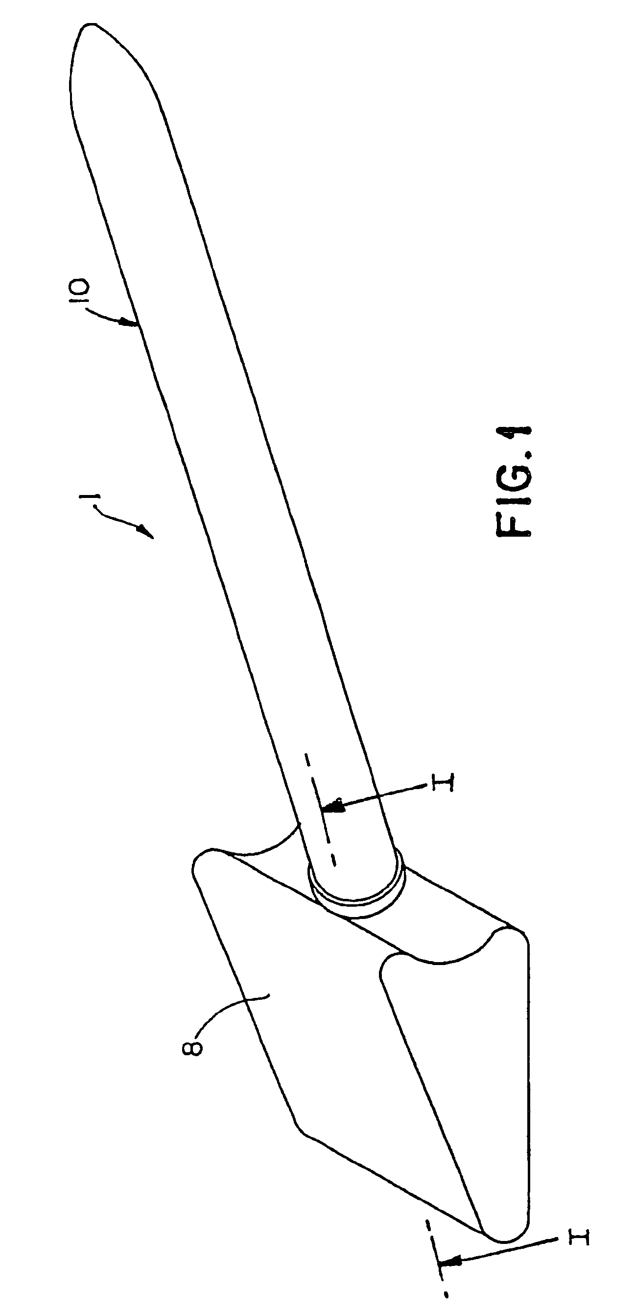
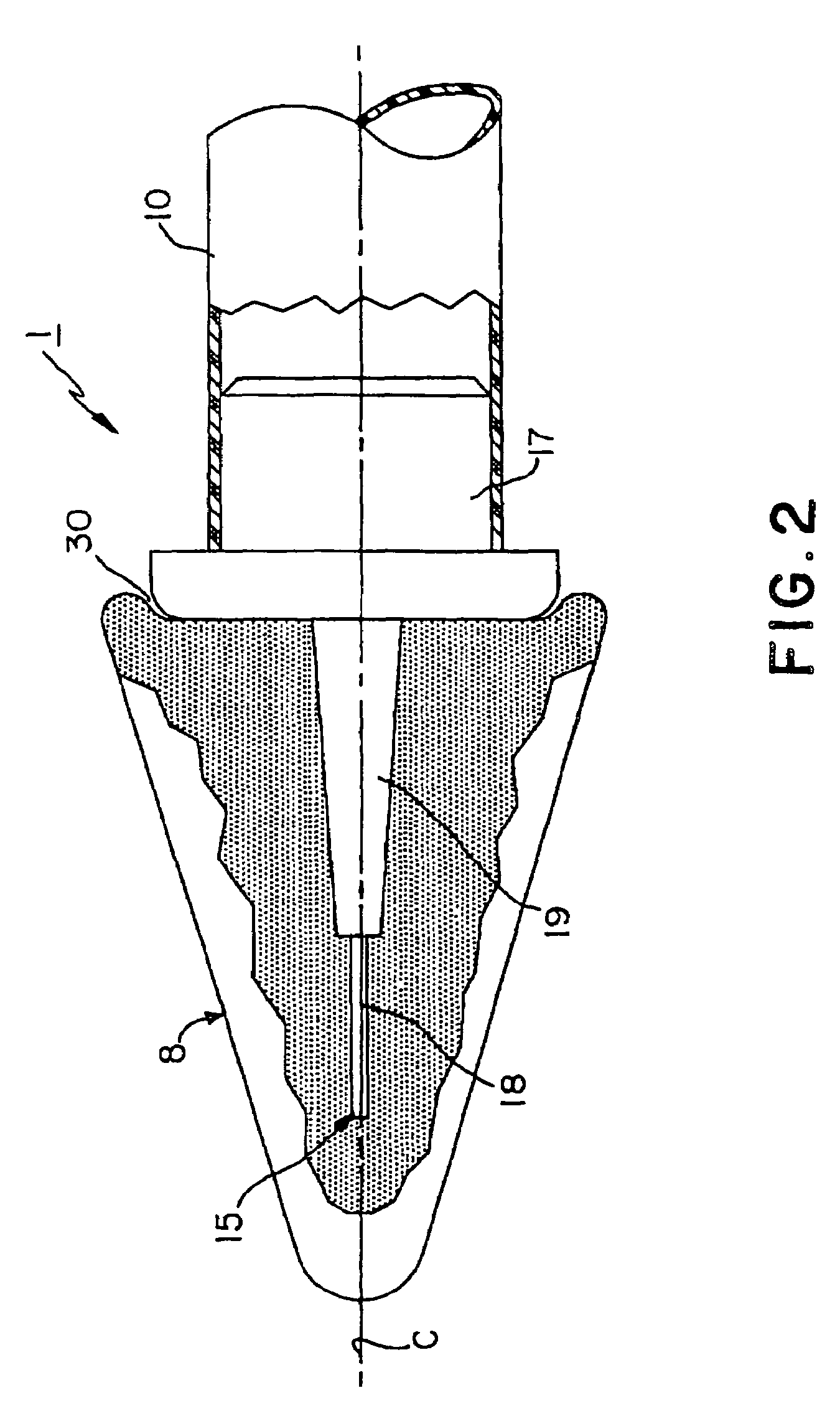
[0029]Referring to the drawings, FIGS. 1 and 2 in particular, illustrate a dispensing applicator according to the present invention generally indicated as reference numeral 1. Dispensing applicator 1 comprises an absorbent applicator member 8, a fluid source 10, and an applicator tip 15. Absorbent member 8 may be of any suitable shape, such as cubic, cylindrical, or conical, and comprise any suitable absorbent material, such as cotton or sponge. Fluid source 10 may have any suitable shape. As shown in FIG. 1, fluid source 10 is preferably a hollow, generally cylindrical body. The end of fluid source body located adjacent to absorbent member 8 is preferably sealed thereto at a joint or seam 30, such as by heat sealing, to enclose the fluid substance contained within fluid source body 10. Applicator tip 15 comprises an attachment member 17 and tongue member 18 joined thereto by a tapered frangible region or juncture 19. Tongue member 18 is preferably a flat and broad shape that extend...


PUM


Abstract

The present invention relates to a hand-held dispensing applicator comprising a source of fluid, a frangible applicator tip attached to the fluid source, and an absorbent member attached to the frangible applicator tip. When the frangible applicator tip is broken, fluid flows from the source to the absorbent member, whereby the fluid is applied and spread on a surface. Preferably, the frangible applicator tip comprises a support element permanently connected to the fluid source, a relatively rigid tongue element extending outwardly of the support element, and a frangible region therebetween. Preferably, the tongue element comprises ribs for reinforcing the tongue element to resist unintentional breaking of the frangible region. More preferably, the applicator tip comprises a semi-permeable or non-permeable cover disposed around the frangible region to control the speed and direction of the dispersion of the fluid in the absorbent member. Adaptive embodiments allow the generation of designs applicable to a particular medical purpose.

Description

FIELD OF THE INVENTION[0001]The present invention is directed in general to means for swabbing a surface (i.e., skin) that is gripped by a user at one end and has a sponge or absorbent material at the other end. Further, the present invention is directed to such means for swabbing a surface having a source of a fluid (e.g., disinfectant or medicament) in communication with the sponge or absorbent material. Specifically, the present invention is directed to such a fluid-containing means for swabbing a surface further having means that is fractured or separated for the purpose of allowing the fluid to flow from the fluid source to the sponge or absorbent material.BACKGROUND OF THE INVENTION[0002]Applicators consisting of a wooden or plastic tube having a bud of cotton on one or both ends, are widely used for numerous purposes, such as the topical application of substances to the human body. A demand exists for a product of this kind which serves not only as an applicator, but also as ...

Claims


Application Information

Patent Timeline
Patent Type & Authority Patents(United States)
IPC IPC(8): B43K5/14
CPCB43M11/06A61M35/006A61M35/003A61M2210/04
Inventor KAUFMAN, JACK W.BROWN, JAMES
Owner BIOMED PACKAGING SYST
Why Eureka
Try Eureka