
Weighing cell including parallel guiding mechanism configured to transmit signals

a technology of parallel guiding mechanism and transmitting signal, which is applied in the direction of force/torque/work measurement apparatus, weighing apparatus details, weighing apparatus using counterbalance, etc., can solve the negative influence of the zero point of the direct-measuring system, the introduction of errors into the weighing, and the inoperable balance. achieve the effect of smallest possible amoun

Active Publication Date: 2009-11-17
METTLER TOLEDO GMBH
View PDF14 Cites 5 Cited by
  • Summary
  • Abstract
  • Description
  • Claims
  • Application Information

AI Technical Summary

Benefits of technology

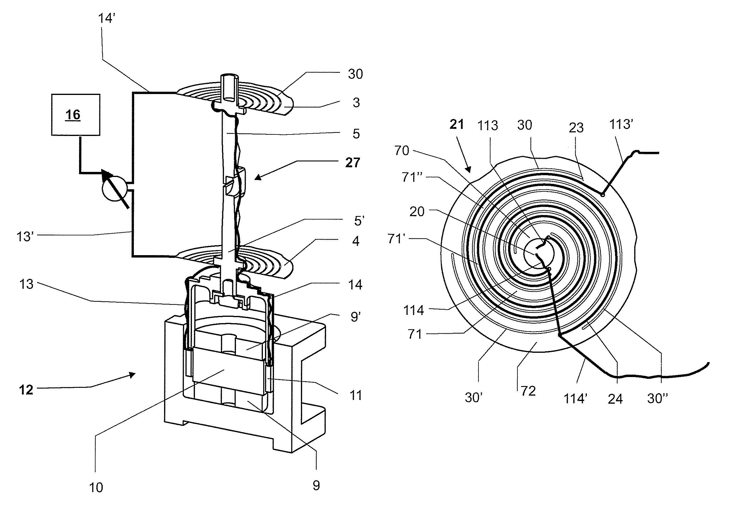
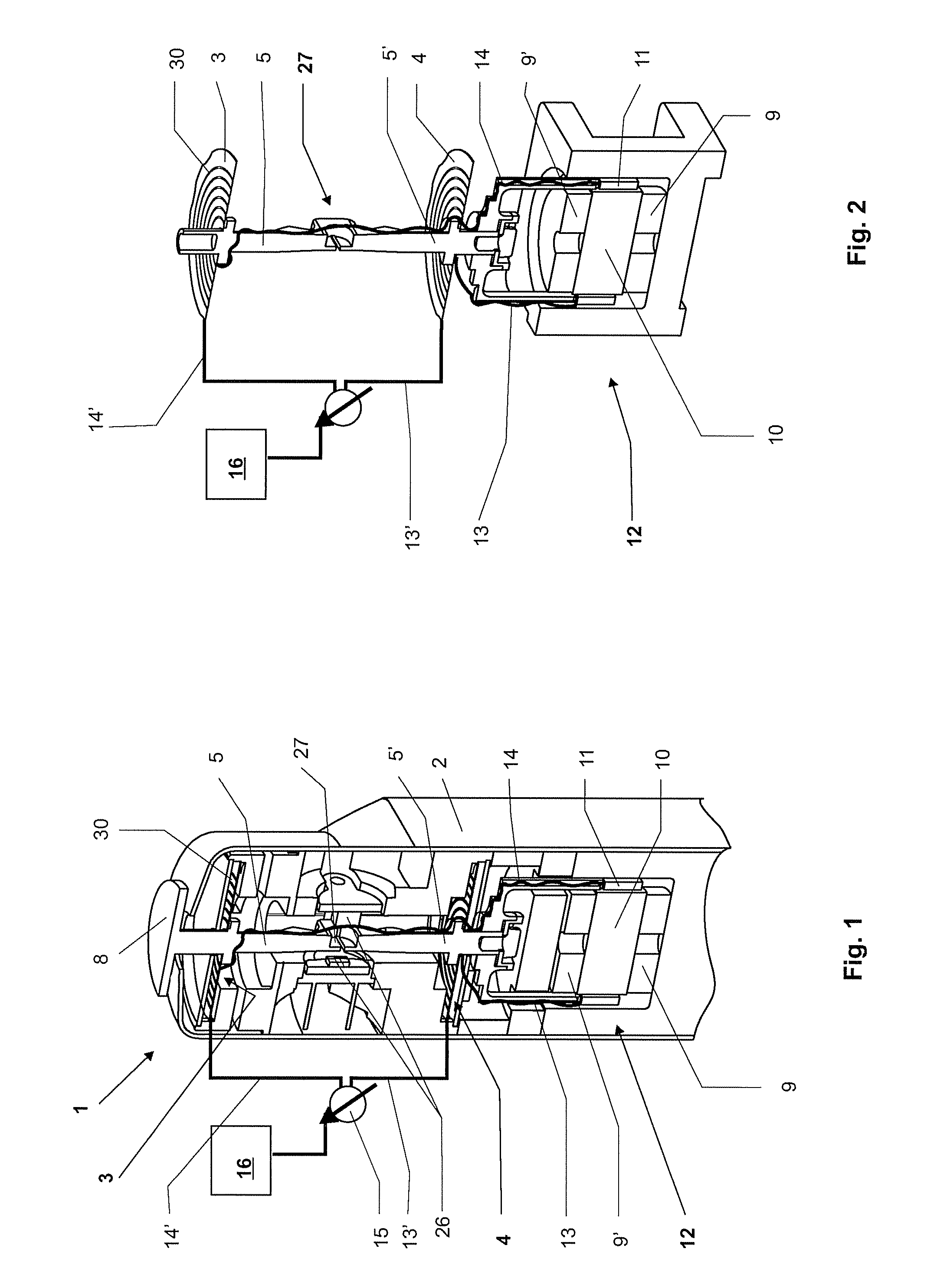
The patent is about a system that allows for the direct measurement of electrical signals without the need for an extra spring constant. The system also aims to have minimal drift at zero points. It includes a mechanism for guiding and compensating for electromagnetic forces using a permanent magnet and coil. The system can transmit both analog and digital signals.

Problems solved by technology

This arrangement has the disadvantage that in addition to providing the electrical connection, the wires also establish a mechanical connection from the stationary to the movable part of the weighing cell.
This introduces an additional spring constant into the direct-measuring system, which interacts with the parallel-guiding mechanism and can introduce errors into the weighing result.
However, the wire filaments are difficult to connect and it can easily happen that one of the wires breaks loose, making the balance inoperable.
It has further been found in particular in compact weighing modules with direct-measuring systems for multi-module weighing devices of the type disclosed for example in EP 1726926 A1, that the drift of the zero point of a direct-measuring system is negatively affected if the parts of the parallel-guiding mechanism and / or of the force-transmitting rod that are connected to the position sensor exhibit a different amount of thermal expansion.

Method used


Image

  • Weighing cell including parallel guiding mechanism configured to transmit signals
  • Weighing cell including parallel guiding mechanism configured to transmit signals
  • Weighing cell including parallel guiding mechanism configured to transmit signals

Examples


Embodiment Construction

[0020]A parallel-guiding mechanism with a plurality of components and a component of the parallel-guiding mechanism as disclosed can be used in the sense of a parallel-guiding mechanism consisting of a plurality of structural parts as well as a parallel-guiding mechanism with a plurality of functional portions or operating parts.

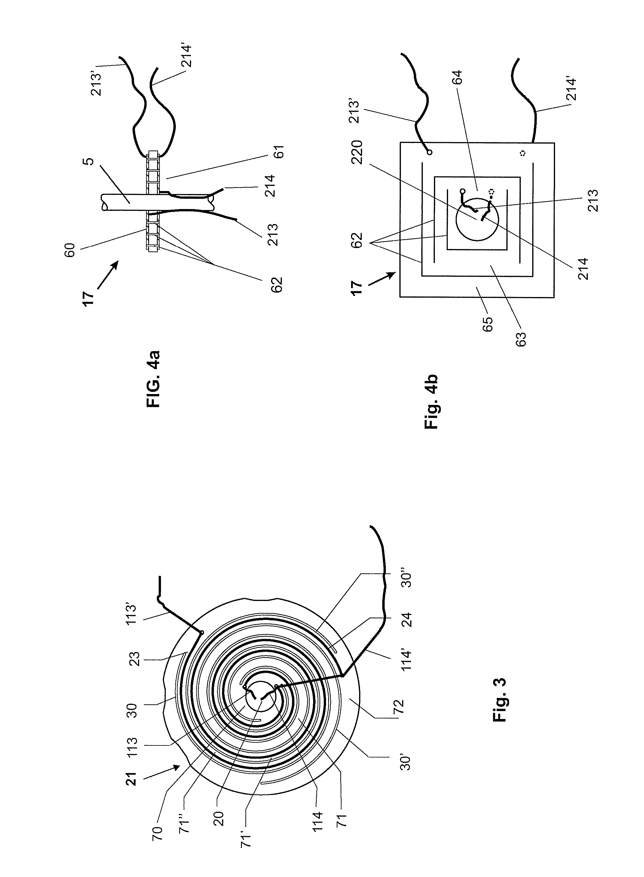
[0021]By transmitting electrical signals through at least one component of the parallel-guiding mechanism, it becomes possible to transmit these signals without introducing an additional mechanical connection between the stationary and the movable part of the weighing cell, whereby for example the measurement accuracy, the stability of the zero point as well as the reproducibility of the weighing cell can be improved.

[0022]The component of the parallel-guiding mechanism can be electrically tied into the control circuit and serves for the transmission of electric currents and / or power.

[0023]The concept of tying the component of the parallel-guiding mechanism ...


PUM


Abstract

An electromagnetic force-compensation direct-measuring system is disclosed. Referred to as direct-measuring system, it comprises a parallel-guiding mechanism; and a load receiver connected with the parallel-guiding mechanism and connected to a force-compensation device by a force-transmitting rod. The force-compensation device can include at least one permanent magnet and a coil that is electrically connected to a control circuit. At least one component of the parallel-guiding mechanism is configured to transmit electric signals.

Description

RELATED APPLICATIONS[0001]This application claims priority under 35 U.S.C. §119 to EP Application 06124719.3 filed in Europe on Nov. 24, 2006, the entire contents of which are hereby incorporated by reference in their entireties.TECHNICAL FIELD[0002]The disclosure relates to an electromagnetic force-compensation direct-measuring system with a load receiver and a force-compensation device which includes a coil and a permanent magnet.BACKGROUND INFORMATION[0003]An electromagnetic force-compensation direct-measuring system, hereinafter referred to as direct-measuring system, is distinguished by the fact that the load receiver is connected through a force-transmitting rod directly to the force compensation device.[0004]Under the principle of electromagnetic force compensation, the force that is caused by a load resting on the weighing pan or on the load receiver is counterbalanced by a force-compensation device consisting of at least one permanent magnet and a coil, wherein the current ...

Claims


Application Information

Patent Timeline
Patent Type & Authority Patents(United States)
IPC IPC(8): G01G7/00
CPCG01G21/244G01G7/02
Inventor BURKHARD, HANS-RUDOLFBENDLER, MARKUS
Owner METTLER TOLEDO GMBH
Learn More