Electrical wiring device

a technology of electrical wiring and wires, applied in the direction of emergency protective circuit arrangements, emergency protective arrangements for limiting excess voltage/current, electric apparatus, etc., can solve the problems of unintended current path, electrical shock hazards, hot conductors may contact ground, etc., and achieve the effect of protecting against damag

Inactive Publication Date: 2009-11-17
PASS SEYMOUR
View PDF14 Cites 14 Cited by
  • Summary
  • Abstract
  • Description
  • Claims
  • Application Information

AI Technical Summary

Benefits of technology

[0013]The present invention addresses the needs described above by providing a protective device that detects the wiring state of the device and inhibits device operation if the device is miswired. The protective device of the present invention also has an indicator lamp which lights when the device is in the tripped condition and turns off when the device is reset. If the device is miswired after having been wired properly, the indicator lamp does not light when the device is tripped, and so provides a supplemental indication of miswiring. The protection circuit is powered from the hot line bus bar. The indicator lamp is also powered via the hot line bus bar of the interrupting contacts to meet safety standards. The protective device of the present invention also includes circuitry that more effectively guards against damage from transient voltage surges.

Problems solved by technology

However, certain types of faults have been known to occur in electrical wiring systems.
A ground fault occurs when a current carrying (hot) conductor creates an unintended current path to ground.
The unintended current path represents an electrical shock hazard.
First, the hot conductor may contact ground if the electrical wiring insulation within a load circuit becomes damaged.
This scenario represents a shock hazard.
For example, if a user comes into contact with a hot conductor while simultaneously contact ground, the user will experience a shock.
A ground fault may also occur when the equipment comes in contact with water.
A ground fault may also result from damaged insulation within the electrical power distribution system.
A ground fault creates a differential current between the hot conductor and the neutral conductor.
The GFCI is sensitive to differential currents that represent an imminently dangerous condition, such as the presence of a current path other than the intended path of normal operation (i.e., a shock hazard).
One problem associated with protective devices relates to the device being miswired in the filed by an installer.
Miswiring may result in the protective device not protecting the user from the fault conditions described above.
However, instructive material may be ignored by an installer.
Another problem is that protective device, like all electrical devices, have a limited life expectancy.
When the device has reached end of life, the user may not be protected from the fault condition.
One drawback to this approach lies in the fact that if the user fails to use the test button, the user will not know if the device is functional.
Transient voltages are known to damage a protective device / cause an end of life condition.
Whatever the cause, transient voltages are known to damage a protective device and cause an end of life condition.

Method used


Image

  • Electrical wiring device
  • Electrical wiring device
  • Electrical wiring device

Examples


Embodiment Construction

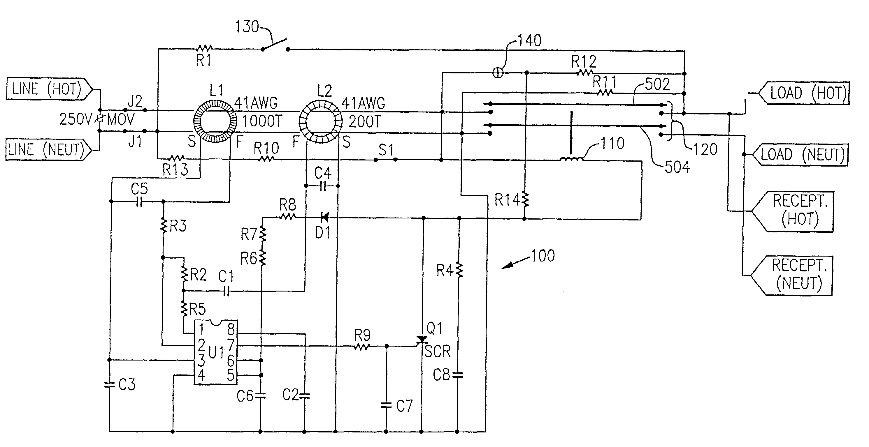
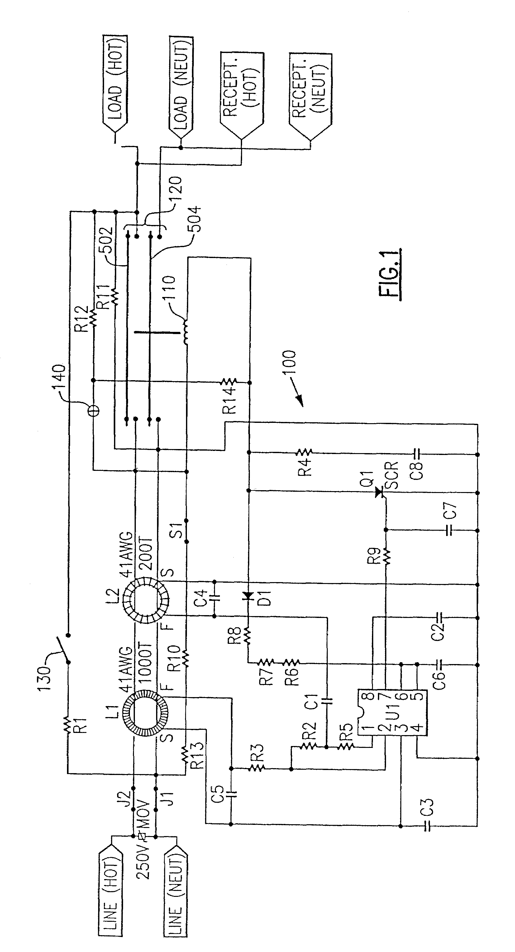
[0024]Reference will now be made in detail to the present embodiments of the invention, examples of which are illustrated in the accompanying drawings. Wherever possible, the same reference numbers will be used throughout the drawings to refer to the same or like parts. An exemplary embodiment of the wiring device of the present invention is shown in FIG. 1, and is designated generally throughout by reference numeral 100.

[0025]As embodied herein and depicted in FIG. 1, a schematic of a GFCI circuit with miswire protection and an indicator lamp 140 in accordance with an embodiment of the invention is disclosed. The GFCI 100 includes sensing transformers L1 and L2. These transformers are coupled to detector U1. The ground fault circuit sensing electronics of GFCI circuit 100 derives power from the line side terminals of the GFCI. When differential transformer L1 senses unequal amounts of current flowing in the hot and neutral conductors due to a ground fault condition, circuit 100 cau...


PUM


Abstract

The present invention is directed to a protective device that includes a hot line terminal, a neutral line terminal, a hot load terminal, and a neutral load terminal. A low pass filter circuit has a capacitor coupled in series with a solenoid coil of the protective device. The low pass filter is coupled across the hot line terminal and the neutral line terminal. A miswire detection circuit is configured to detect a miswire fault condition when AC power is coupled to the hot load terminal and the neutral load terminal. An interrupting contact assembly includes interrupting contacts that provide electrical continuity between the hot line terminal and the hot load terminal and the neutral line terminal and the neutral load terminal in a reset state. The interrupting contacts are open in a tripped state. An indicator circuit is coupled to the interrupting contact assembly and being configured to indicate the tripped state and / or the reset state.

Description

CROSS-REFERENCE TO RELATED APPLICATIONS[0001]This is a continuation of U.S. patent application Ser. No. 10 / 884,304 filed on Jul. 2, 2004, which is a continuation of U.S. Pat. No. 6,856,498 filed on Oct. 5, 2001, which is a continuation of U.S. Pat. No. 6,522,510 filed Nov. 21, 2000, the contents of which are relied upon and incorporated herein by reference in their entirety, and the benefit of priority under 35 U.S.C. §120 is hereby claimed.BACKGROUND OF THE INVENTION[0002]1. Field of the Invention[0003]The present invention relates generally to electrical wiring devices, and particularly to protective wiring devices.[0004]2. Technical Background[0005]An electrical distribution system provides power to a house, building or some other facility. Electrical wiring from a power utility provides AC power to one or more breaker panels disposed in the structure. The breaker panel distributes AC power to one or more branch electric circuits installed in the structure. The electric circuits ...

Claims


Application Information

Patent Timeline
Patent Type & Authority Patents(United States)
IPC IPC(8): H02H3/00
CPCH02H3/338
Inventor FINLAY, SR., DAVID A.PACKARD, THOMAS N.
Owner PASS SEYMOUR
Why Eureka
Try Eureka