Segmented foundation installation apparatus and method

a technology of anchoring device and support device, which is applied in the direction of building repair, building material handling, construction, etc., can solve the problems of inconvenient installation, inconvenient transportation and handling, and limited number of anchoring devices, etc., and achieves convenient handling, less expensive, and convenient access

Inactive Publication Date: 2009-11-24
METAL FOUND ACQUISITION
View PDF216 Cites 32 Cited by
  • Summary
  • Abstract
  • Description
  • Claims
  • Application Information

AI Technical Summary

Benefits of technology

[0025]The apparatus and method of the present invention provide for installation of a novel segmented foundation and anchoring device of any required length. The installation of the novel segmented foundation uses an anchoring device manufactured in a multitude of lengths, e.g., in one aspect in increments of six inches. The apparatus and method of the present invention provide for installing a segmented foundation which is less expensive and much easier to handle while providing any length required. The apparatus and method of the present invention provide for installing a segmented foundation that can be readily available in the field and easy to assemble in the field to match any required length, eliminating the need to install special lengths. The novel segmented foundation and anchoring device eliminate the need to drill a deeper earthen hole, when the installer is forced to use a longer anchoring device, by providing the installer with apparatus and methods to match any length required by the foundation to be installed with it, and meet any unforeseen length requirement because of unexpected soil conditions. The apparatus and method of the present invention provide for installing a novel segmented foundation and anchoring device which always exert the installation forces upon the soil instead of exerting the forces upon its components, and which are easily retrievable, even when the top portion falls down below the surface, at the top of the earthen hole it was installed in.

Problems solved by technology

One drawback of the conventional anchoring device is they are made only in one-piece full lengths, making them expensive to transport and to handle.
Another drawback is the conventional anchoring device is manufactured only in a limited number of standard lengths, while the SAFE Foundations installed with these devices are manufactured in a multitude of lengths, in increments of six inches.
When the installer cannot find a standard anchoring device length, he / she is forced either to install a longer standard length than the actual length required, or the installer is forced to have one special anchoring device made to order, i.e., specially custom ordered of the required size, which means more expensive and time consuming installations.
Yet another drawback is when the installer is forced to utilize a longer-than-required anchoring device.
This translates into additional costs.
Still another drawback exists despite the fact that the characteristics of the soil are known in advance where the SAFE Foundation is to be installed and the length of anchoring device is determined.
In such situations, deeper holes have to be augered, requiring longer anchoring devices, standard or not, to be utilized and therefore not instantly available at the installation site.
These unexpected developments create installation delays as well as cost overruns.
A further drawback involves the forces required for stressing the conventional anchoring assembly.
At some point during the installation of the anchoring device, force is exerted on the components of the device, instead of being exerted upon the soil, because of its “mechanical stop” that serves as “limiting means.” This can provide false readings of the strength of the installation.
Another drawback is the need for large equipment to lift the anchor because of the weight of the long anchor assembly.
Yet a further drawback is that the conventional anchoring device is very difficult to retrieve from inside its earthen hole, if after the installation is complete its top portion falls below grade, i.e., below the top surface of the earthen hole it was installed in.

Method used


Image

  • Segmented foundation installation apparatus and method
  • Segmented foundation installation apparatus and method
  • Segmented foundation installation apparatus and method

Examples


Embodiment Construction

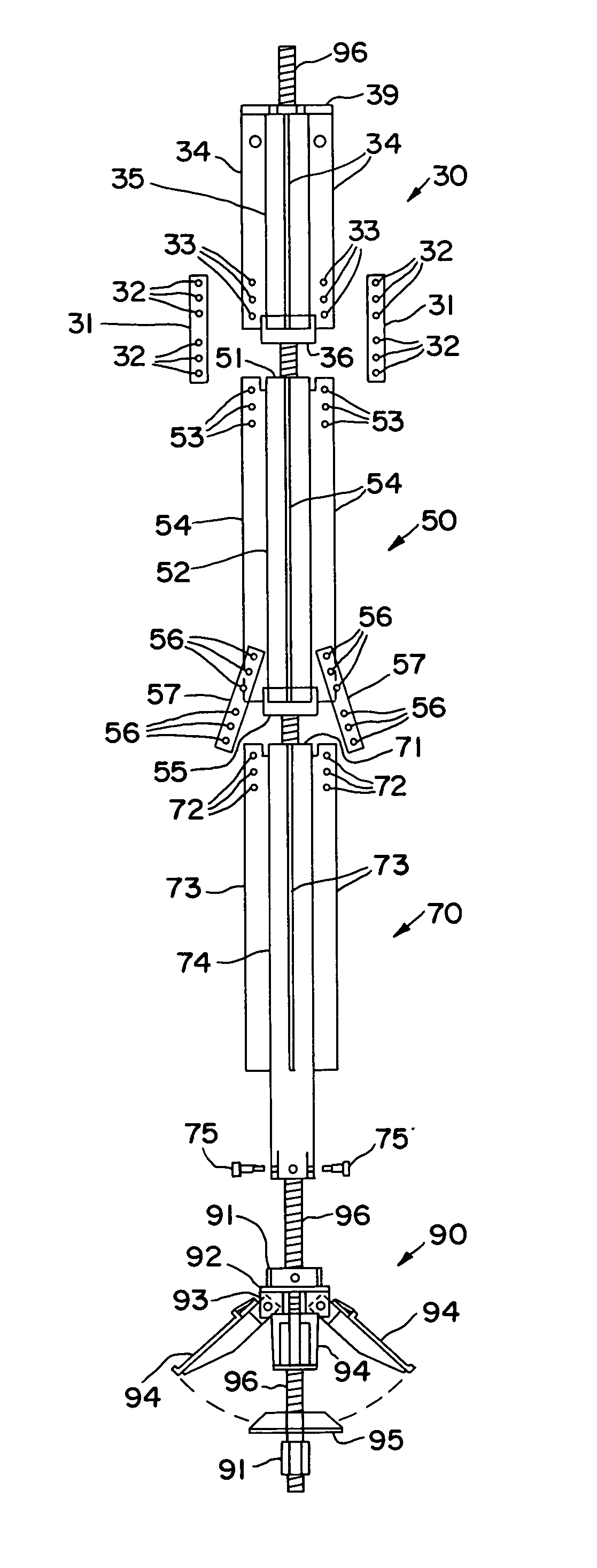
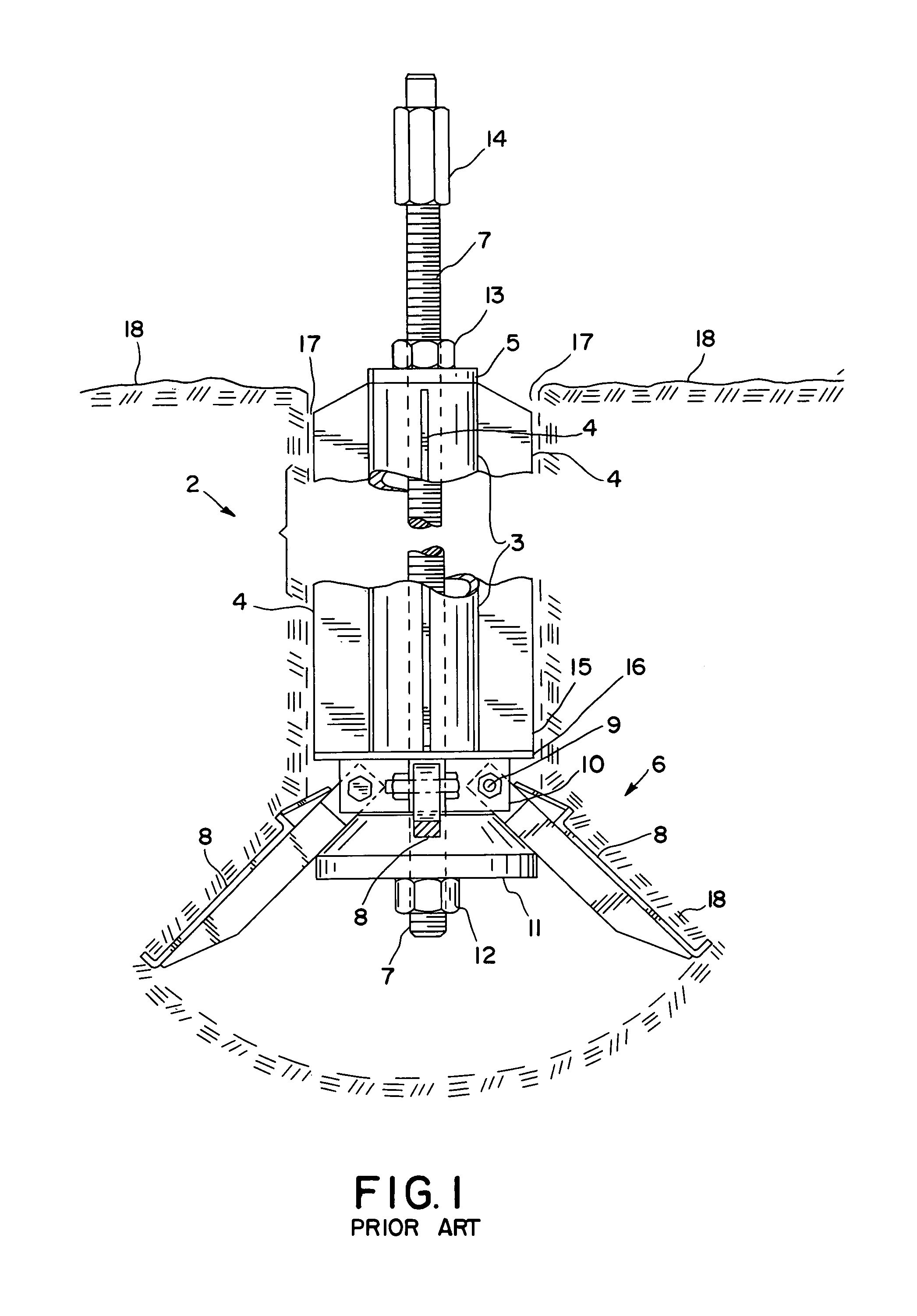
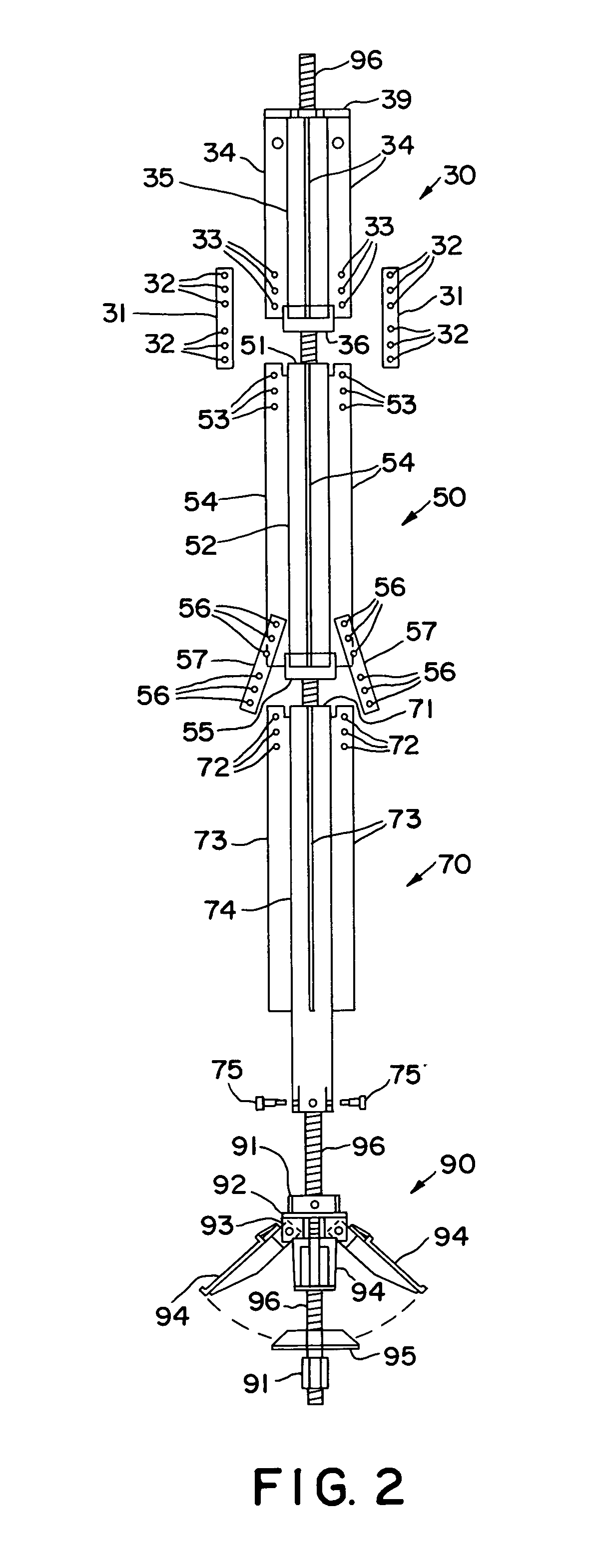
[0042]FIG. 1 shows a foundation anchoring and support assembly 2 utilized for the installation of a SAFE Foundation in the ground. FIG. 1 shows a one-piece foundation-guiding column 2, shown cut-away in order to show one-piece, standard threaded rod 7 going through the inside of a one-piece pipe column 3. Anchoring assembly 2 is shown already installed, inside earthen hole 17, in soil 18.

[0043]Foundation-guiding column 2 includes a one-piece length of steel pipe 3, with three or four fins 4 welded along vertical surface 3 and at ninety degrees from each other. A top plate 5 is welded to the top end of pipe 3.

[0044]FIG. 1 also shows an anchoring head assembly 6, including one-piece threaded rod 7, four pivoting compaction and consolidation plates 8 (only two are fully shown and one is partially shown) which pivot around bolts 9, also support frame 10 with plate 16 welded to it, frusto-cone 11 held in position by nut 12, which is threaded-on to the bottom end of threaded rod 7.

[0045]B...


PUM


Abstract

Vertical segmented support and media consolidation plates swingably mounted about pivot points on the vertical segmented support, incorporate media-facing surfaces swingable outwardly from the vertical support means into the surrounding media. Varying segmented lengths form the segmented vertical segmented support. The novel segmented apparatus and installation method further provide for a centering collar 113, an anchor positioning means at level force pivoting plates 194, and pivoting plates 194 positioned 40-50 degrees from vertical. A frusto-cone 197 dx equal to a predetermined distance of one-half inch forms gap 204. The novel method installs an anchor and foundation device in the earth by preparing a hole in the earth, lowering into the hole a segmented anchor or foundation device having swingable media facing plates, and applying force to swing the plates outwardly into the surrounding media.

Description

[0001]This patent application is a continuation-in-part of prior, U.S. patent application Ser. No. 60 / 331,879, filed Nov. 20, 2001.BACKGROUND OF THE INVENTION[0002]1. Technical Field[0003]This invention relates to a segmented anchoring and support apparatus utilized as a tool for the installation of finned and non-finned tubular foundations. In one aspect, this invention relates to a method of installation of foundations in the ground utilizing the apparatus of the invention. In one aspect, this invention relates to the utilization of the apparatus and methods of this invention for the installation of SAFE Foundations Secure Anchoring and Foundation Equipment.[0004]2. Background[0005]Tubular foundations are utilized for supporting structures, e.g., lighting poles, across-the-highway traffic signs, communication towers, and others. Tubular foundations are installed in the ground by pressing them into the soil utilizing hydraulic power means and a pre-stressed, conventional anchoring ...

Claims


Application Information

Patent Timeline
Patent Type & Authority Patents(United States)
IPC IPC(8): E04B1/00E02D5/80E02D27/42
CPCE02D5/803E02D5/805E02D27/42
Inventor REINERT, SR., GARY L.
Owner METAL FOUND ACQUISITION
Why Eureka
Try Eureka