Removal device and method for vertical blinds

a vertical blind and slat technology, applied in the field of vertical blinds, can solve problems such as damage and/or operator injury, and achieve the effects of reducing the risk of injury, quick and easy release of the vertical blind slat, and reducing the tim

Inactive Publication Date: 2009-11-24
FIGURA JOHN JOSEPH +1
View PDF6 Cites 0 Cited by
  • Summary
  • Abstract
  • Description
  • Claims
  • Application Information

AI Technical Summary

Benefits of technology

[0008]The primary objective of this invention is to provide a removal device that quickly and easily releases a vertical blind slat from the fastener suspending it in place, without causing damage to the slat, the fastener, the device, or surrounding areas. It is also an objective of this invention to provide a removal device for vertical blind slats that reduces the time an operator must spend on an elevated support surface for slat replacement and also substantially reduces the risk of injury to an operator using it for slat removal as compared to slat removal using an elongated tool, such as a screwdriver. Another objective of this invention is to provide a removal device that is small, hand-held, and easily manipulated by an adult human hand. Yet another objective of this invention is to optionally provide a removal device that can illuminate the top end of a vertical blind slat for fast and easy engagement of the operative portion of the removal device with the fastener holding the slat in place. It is also an objective of this invention to provide a removal device having sturdy construction and simple low cost manufacture.

Problems solved by technology

In the alternative, using a screwdriver or other tool to release the slat from the C-shaped clip can easily lead to damage and / or operator injury since slat release is accomplished with outstretched and elevated arms.

Method used


Image

  • Removal device and method for vertical blinds
  • Removal device and method for vertical blinds
  • Removal device and method for vertical blinds

Examples


Embodiment Construction

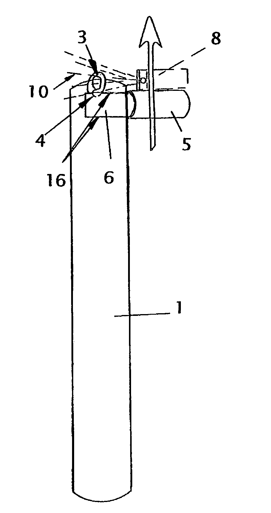
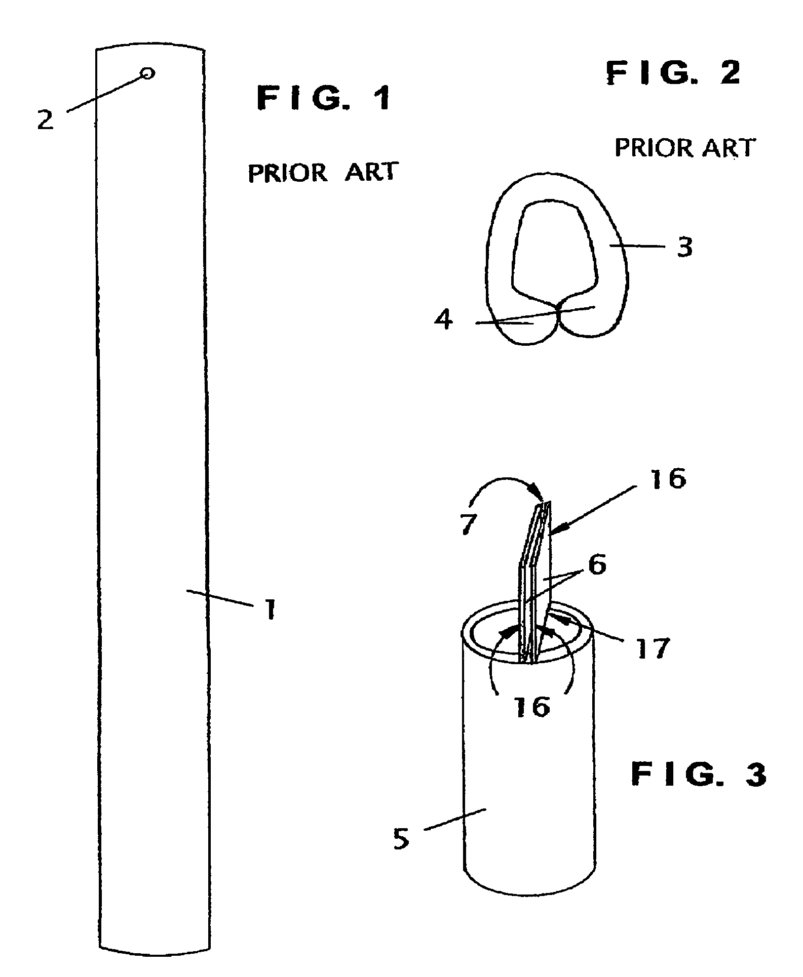
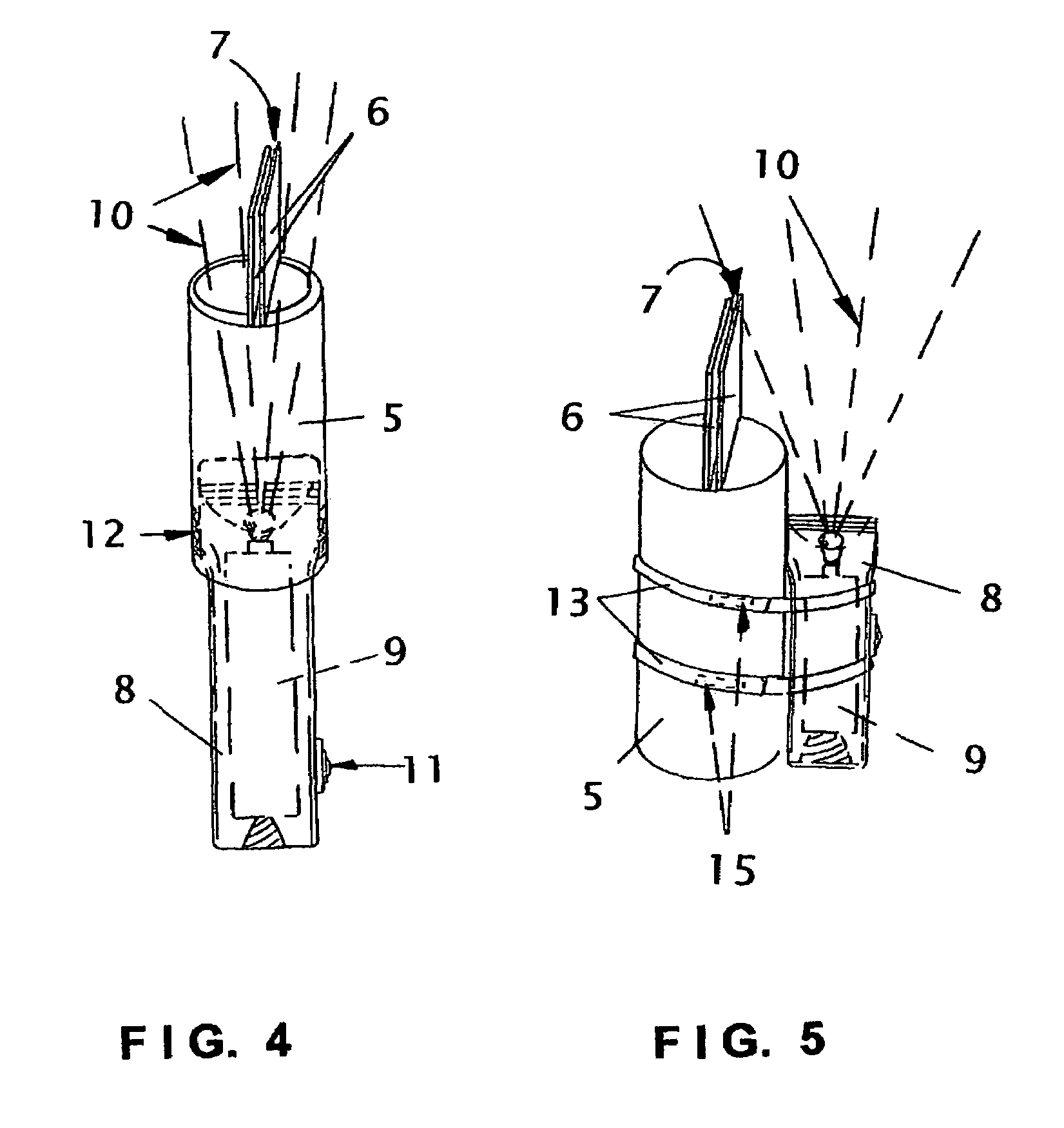
[0018]FIGS. 1 and 2 respectively show examples of a typical vertical blind slat 1 with a connection hole 2 near its top end, and a C-shaped fastener 3 commonly used with hole 2 to connect vertical blind slat 1 in a suspended position of use wherein it can be pulled along an overhead track to adjust the amount of outside light reaching the interior space collectively behind multiple slats 1 suspended from the same overhead track. FIG. 2 shows the tightly-biased ends 4 of C-shaped fastener 3 that must be forced open by one of the lateral edges 16 of each projection 6 of the present invention to allow a slat 1 to drop away from its suspended position of use. FIGS. 3-6 show four alternative embodiments of the present invention. First, FIG. 3 shows a main body 5 and two projections 6 secured across one end of main body 5 in a closely spaced-apart configuration that creates an open-sided and open-ended slot 7, since neither projection 6 is attached to the other. Then, in contrast, FIGS. 4...


PUM


Abstract

A removal device and method of use that allows easy detachment of a suspended vertical blind slat's upper end from the generally C-shaped clip or other openable fastener suspending the slat for movement along a track. The device has a tubular and / or cylindrical configuration with preferred length and diameter dimensions of approximately four and two inches, respectively. Clip-releasing projections are connected across one end of the main body, in positions closely spaced apart from one another, but not in contact with one another. A light source can be optionally attached to the removal device in several configurations, to provide enhanced illumination of the fastener holding the vertical blind slat in place and thereby facilitate alignment of the lateral edges of the projections with the fastener before the needed upwardly-directed dislodging force is applied. Use of the removal device does not injure the projections, the slat, the operator, or the fastener.

Description

CROSS-REFERENCES TO RELATED APPLICATIONS[0001]NoneBACKGROUND OF THE INVENTION[0002]1. Field of the Invention[0003]The present invention relates to vertical blinds, the C-shaped fasteners commonly used to suspend vertical blind slats from an overhead track, and hand-held tools used to open the tightly-biased ends of a C-shaped fastener to release a suspended vertical blind slat from its usable position, specifically to a removal device and method of use that allows for prompt and easy detachment of a vertical blind slat from the generally C-shaped fastener connected to the upper end of the slat while it is in its suspended position of use. The present invention device has a rigid main body that in its most preferred embodiment is tubular in construction, and further has two rigid projections extending from one end of the main body. The projections are only connected to the main body, and not to one another. The projections are also closely spaced-apart, and for most effective use, it...

Claims


Application Information

Patent Timeline
Patent Type & Authority Patents(United States)
IPC IPC(8): E05D15/00E06B3/12
CPCE06B9/36
Inventor FIGURA, JOHN JOSEPHFIGURA, BARBARA MINNETTA
Owner FIGURA JOHN JOSEPH
Why Eureka
Try Eureka