Eureka AIR delivers breakthrough ideas for toughest innovation challenges, trusted by R&D personnel around the world.

Electrical card connector with improved card restriction structure

a technology of restriction structure and card connector, which is applied in the direction of coupling device connection, two-part coupling device, electrical apparatus, etc., can solve the problem of terrible affect of signal transmission

Inactive Publication Date: 2009-12-08
HON HAI PRECISION IND CO LTD
View PDF5 Cites 19 Cited by
  • Summary
  • Abstract
  • Description
  • Claims
  • Application Information

AI Technical Summary

Benefits of technology

[0006]Hence, an improved electrical card connector with improved card restriction structure is needed to solve the problem above.

Problems solved by technology

As a results, signal transmission is terribly affected.

Method used


Image

  • Electrical card connector with improved card restriction structure
  • Electrical card connector with improved card restriction structure
  • Electrical card connector with improved card restriction structure

Examples


Embodiment Construction

[0021]In the following description, numerous specific details are set forth to provide a thorough understanding of the present invention. However, it will be obvious to those skilled in the art that the present invention may be practiced without such specific details. In other instances, well-known circuits have been shown in block diagram form in order not to obscure the present invention in unnecessary detail. For the most part, details concerning timing considerations and the like have been omitted inasmuch as such details are not necessary to obtain a complete understanding of the present invention and are within the skills of persons of ordinary skill in the relevant art.

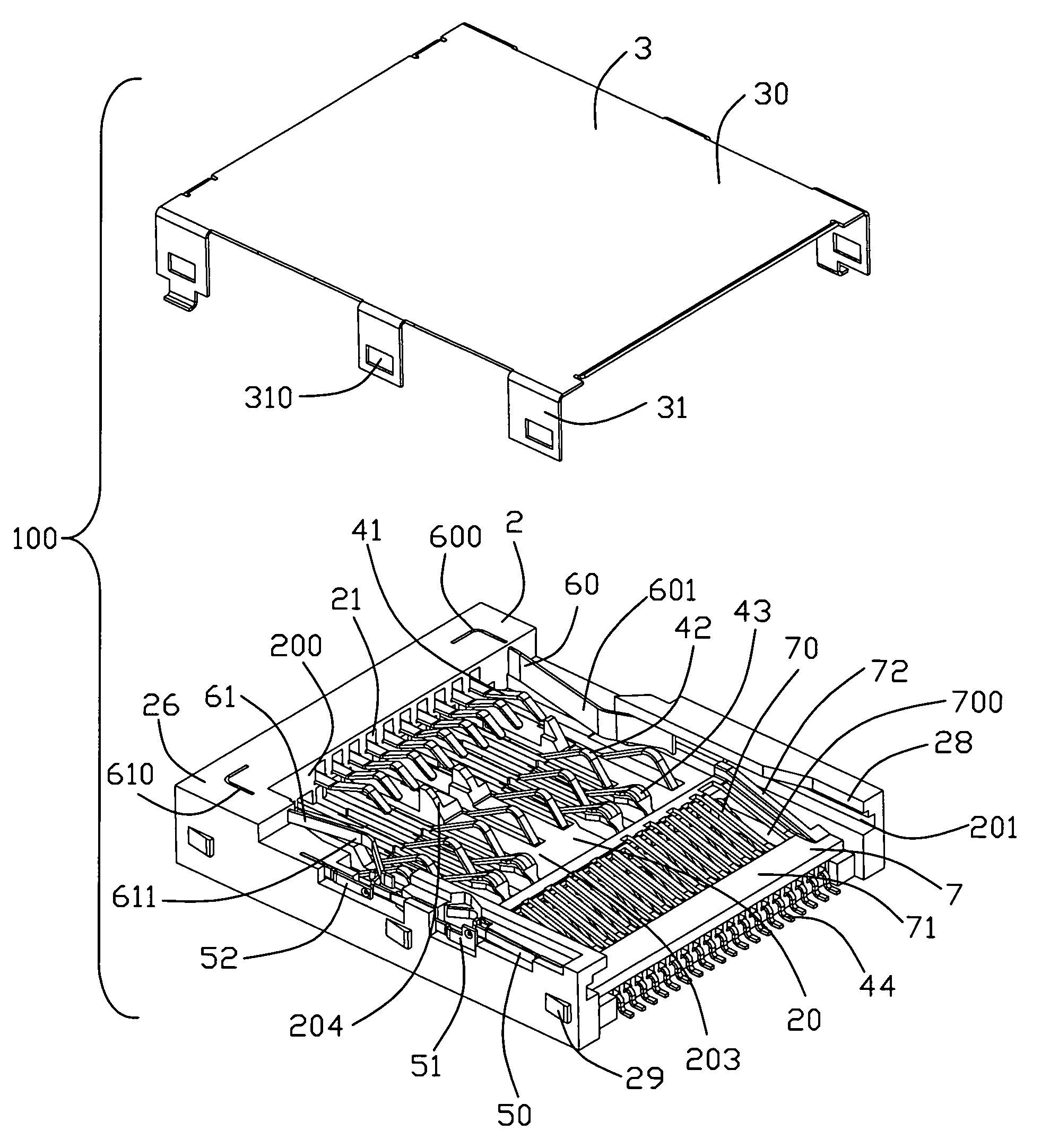
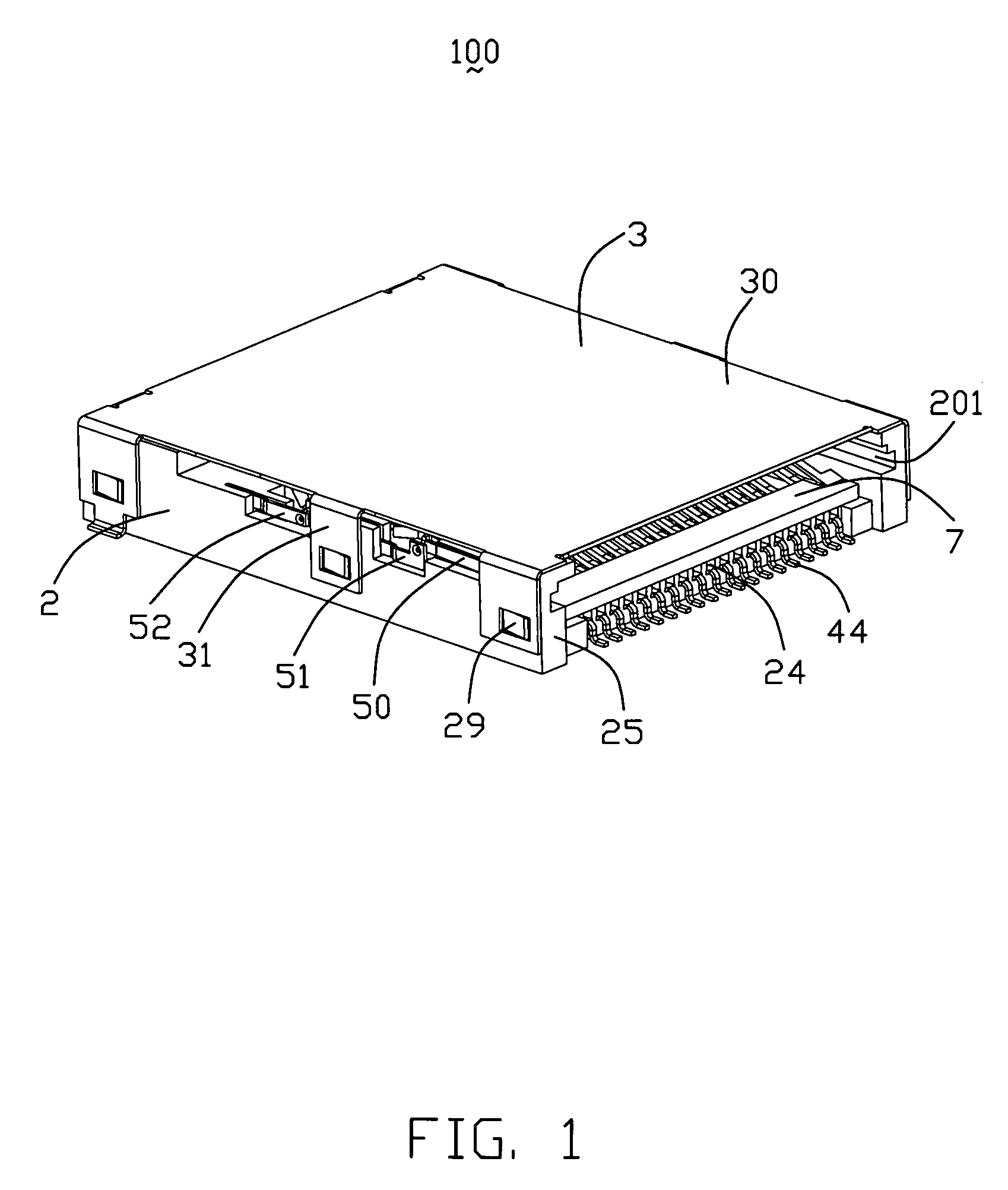
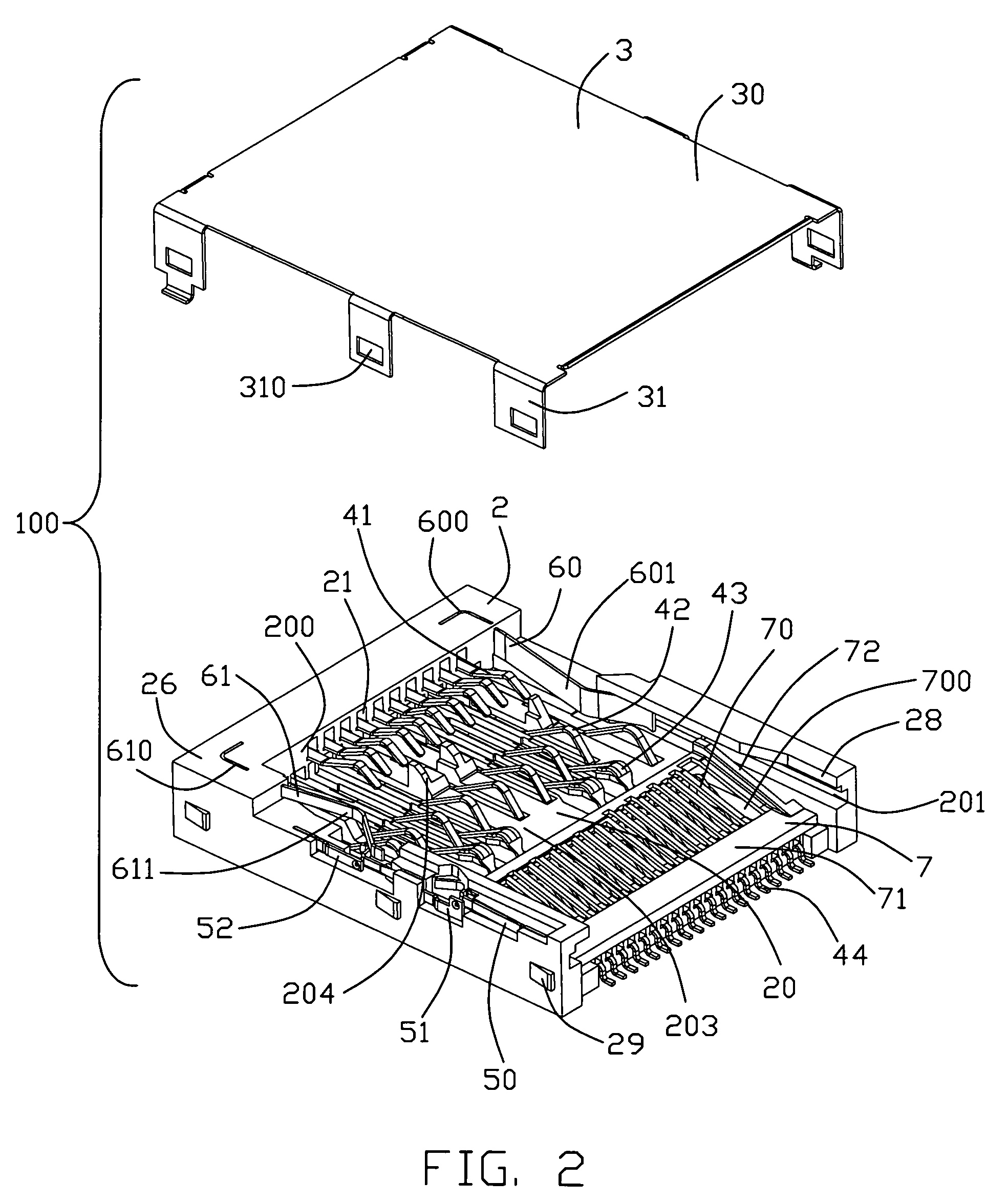
[0022]Referring to FIGS. 1-8, an electrical card connector 100 for being mounted on a PCB (not shown) can be used for insertion of many kinds of cards 8 such as xD card 81, SD card 82, MMC card 83, MMCplus card 84, MS card 85 and MS Duo card 86, as best shown in FIGS. 5 and 6. It is a common knowledge that the ...


PUM


Abstract

An electrical card connector includes an insulative housing defining a card receiving space and a plurality of contacts for mating with a first card and a second card wider than the first card. A card restriction member is fixed to the insulative housing and includes a deformable main body upwardly extending into the card receiving space. The main body includes a pair of raised portions protruding upwardly beyond a guiding surface thereof with a depression formed between said pair of raised portions. With insertion of the first and the second cards into the card receiving space, the first card is received in the depression and restricted by the raised portions, and the second card is restricted by the side walls of the insulative housing for stable guiding insertion.

Description

BACKGROUND OF THE INVENTION[0001]1. Field of the Invention[0002]The present invention relates to electrical card connectors, more particularly to electrical card connectors with improved card restriction structure for restricting and guiding insertion of corresponding cards.[0003]2. Description of Related Art[0004]Nowadays, memory cards are widely used in electronic devices. There are many kinds of memory cards such as MMC (Multi Media) card, SD (Secure Digital) card, xD (xD-Picture) card, MS (Memory Stick) card and MS (Memory Stick) Duo card. According to the standard specification, the dimension of the MS card is 50 mm×21.5 mm×2.8 mm and the dimension of the MS Duo card is 31 mm×20 mm×1.6 mm. It is obvious that the MS card is much wider and thicker than the MS Duo card.[0005]Electrical card connectors are usually mounted on a PCB of the electronic devices to establish data transmission between the memory cards and the electronic devices. It is a common knowledge to those of ordina...

Claims


Application Information

Patent Timeline
Patent Type & Authority Patents(United States)
IPC IPC(8): H01R24/00
CPCH01R12/7005H01R27/00
Inventor ZHANG, SHI-GUIZHAO, QI-JUNYIN, HUA
Owner HON HAI PRECISION IND CO LTD
Why Eureka
Eureka Blog
Learn More