Positioning device

a technology of positioning device and motor control circuit board, which is applied in the direction of instruments, machine supports, gearing, etc., can solve the problems of increased weight and cost, and increased weight and cost of two motors, so as to reduce the number of motor control circuit boards, reduce the number of mechanisms used, and increase competitiveness and weight

Active Publication Date: 2019-09-26
THALES SA
View PDF9 Cites 4 Cited by
  • Summary
  • Abstract
  • Description
  • Claims
  • Application Information

AI Technical Summary

Benefits of technology

[0007]The invention aims to remedy all or some of the problems cited above by proposing a positioning device comprising a single motor in order to orientate an instrument along two axes. The invention has the advantage of reducing the number of mechanisms used and reducing the number of motor control circuit boards (a gain in competitiveness and in weight) and reducing the size of the electrical harness, thus reducing the restrictions on the deployable structures bearing the mobile antennae and on the deployment mechanisms. This solution represents a gain in cost and weight of approximately 20% relative to the solutions of the prior art.

Problems solved by technology

This type of device is certainly accurate and robust but it requires two rotating actuators which represent increased weight and cost.
Moreover, this solution involves having to control the wire strands of two motors.
This is problematical in the case of using a panel having a plurality of reflectors due to the fact that a resistant torque is generated by the wire strands when the panel is deployed.
Moreover, this solution also requires two motor control circuit boards which contributes to the additional weight and costs.
More specifically, the need for two motors involves increased weight and cost due to the presence of two motors and two motor control circuit boards.
Moreover, the wire strands of the two motors are difficult to control.
In addition to the drawbacks cited above of increased weight and cost, with two actuators and two control circuit boards and the problem of controlling the wire strands, this solution only provides a small swing of + / −1.5°.

Method used


Image

  • Positioning device
  • Positioning device
  • Positioning device

Examples


Embodiment Construction

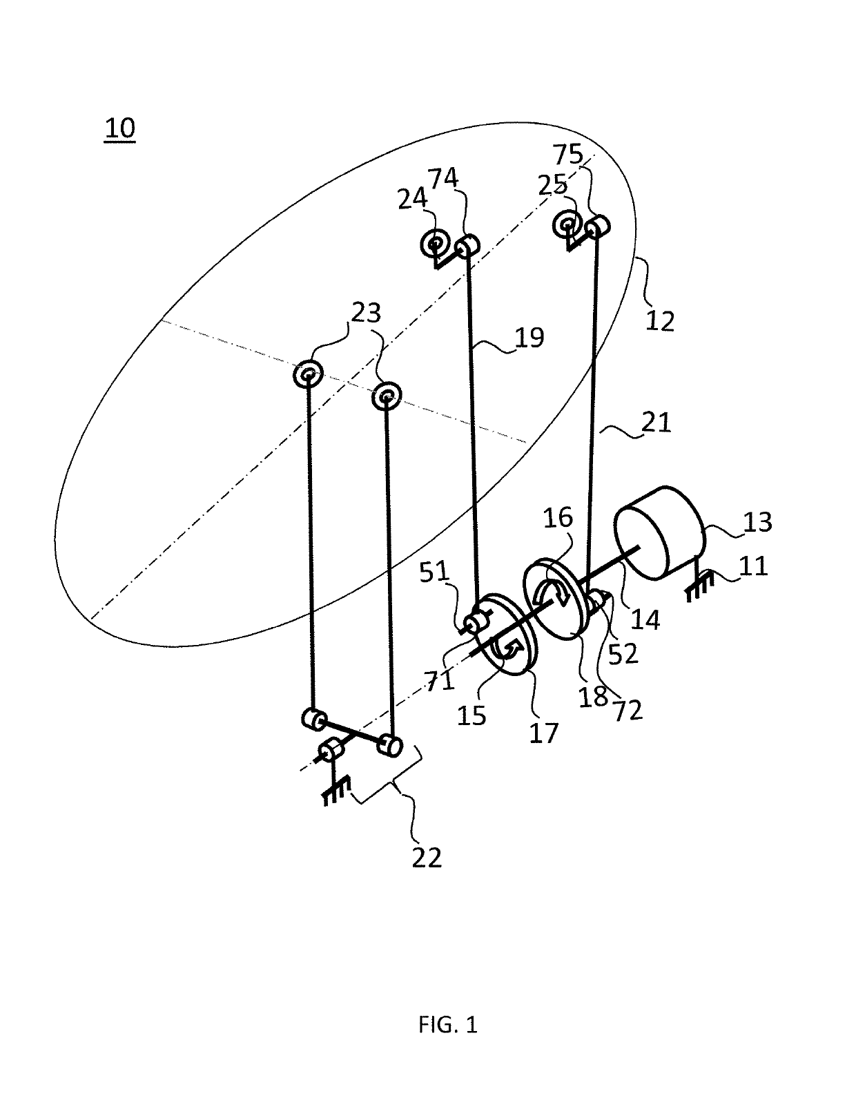
[0030]In the description of the present application, the invention is described within the scope of a space application. As mentioned above, the invention is applicable to any other technical sector which requires the use of a positioning device of any instrument. The invention also applies to the implementation of a relative movement of an object with regard to another object, for example the opening and closing of a shroud.

[0031]FIG. 1 shows a first embodiment of a pointing device 10 of the pointing assembly according to the invention. The pointing device 10 is designed to position and orientate an instrument in a predetermined direction. Within the context of a space application, the instrument is positioned on a plate 12 and may, for example, be an antenna which is desired to be pointed toward a specific location on the surface of the earth, or a reflector. The invention further relates to the opening and closing of a part such as a shroud, in which case the plate 12 which may b...


PUM


Abstract

A positioning device includes a chassis, a plate to be positioned, wherein it further comprises a motor comprising a stator which is connected to the chassis and a rotor,a shaft which is connected to the rotor driven by the motor, which is mobile in rotation relative to the chassis in a first direction and in a second direction opposing the first direction, a first element for the transmission of rotational movement which is configured to be driven in rotation by the shaft in the first direction and to be free in the second direction, a second element for the transmission of rotational movement which is configured to be driven in rotation by the shaft in the second direction and to be free in the first direction, a first connecting rod which is connected to the plate by a first pivot connection and which is connected to the first element for the transmission of rotational movement by a second pivot connection which is offset to the axis of rotation of the first element for the transmission of rotational movement, a second connecting rod which is connected to the plate by a third pivot connection and which is connected to the second element for the transmission of rotational movement by a fourth pivot connection which is offset to the axis of rotation of the second element for the transmission of rotational movement, a connecting element having at least two degrees of rotational freedom between the plate and the chassis.

Description

CROSS-REFERENCE TO RELATED APPLICATIONS[0001]This application claims priority to foreign French patent application No. FR 1800240, filed on Mar. 22, 2018, the disclosure of which is incorporated by reference in its entirety.FIELD OF THE INVENTION[0002]The invention relates to a positioning device which is designed to position an instrument such as an antenna, a reflector or any payload. Whilst the invention is applicable in the space sector, it applies to various other sectors such as the navigation or positioning of any instrument relative to another. A space application of the invention will be taken as an example.BACKGROUND[0003]In space applications it is necessary to be able to orientate specific elements of a satellite or space vehicle, such as an antenna or a reflector, in a predetermined direction, for example in order to direct them toward a fixed star, to keep them pointing toward a location on the surface of the earth or even to scan a specific zone on the surface of the ...

Claims


Application Information

Patent Timeline
Patent Type & Authority Applications(United States)
IPC IPC(8): H01Q1/12G02B7/183H01Q1/28
CPCH01Q1/288H01Q1/125F16M11/14G02B7/183H01Q3/08F16M11/12F16M11/18H02N2/046H02N2/043F16H21/40H02N2/0095
Inventor CALMETTES-CARENSAC, FABIEN
Owner THALES SA
Why Eureka
Try Eureka