Screen member and head-up display apparatus

a display apparatus and screen member technology, applied in the field of screen member and head-up display apparatus, can solve the problems of increasing to each other, and achieve the effect of reducing the brightness unevenness of the display image and restricting the structure of the screen member from being complicated

Active Publication Date: 2016-08-16
DENSO CORP
View PDF22 Cites 4 Cited by
  • Summary
  • Abstract
  • Description
  • Claims
  • Application Information

AI Technical Summary

Benefits of technology

[0007]The present disclosure is made in view of the foregoing issues, and it is an object of the present disclosure to provide a technology regarding a screen member such as a microlens array, which is capable of reducing unevenness of brightness of a display image caused by interference of laser beams while maintaining a simple structure.Means to Solve the Problem
[0009]In the above screen member, the curved shape of the curved surface portion is different between adjacent optical elements, in the cross-section intersecting the scanned surface. Therefore, positions at which the laser beams, which have been diffracted by the curved surface portions, are intensified to each other due to interference are unevenly arranged. As such, when a laser beam for depicting the display image is scanned, the position at which the laser beams are intensified to each other due to the interference moves with time at a speed that the viewer cannot perceive. Therefore, intensity distribution of the laser beams reaching the viewing space can be substantially equalized. As described above, since the curved surface portions having different curved shapes in the cross-section are arranged, it is possible to reduce brightness unevenness of the display image caused by the interference of the laser beams while restricting the structure of the screen member from being complicated.

Problems solved by technology

Therefore, positions at which the laser beams, which have been diffracted by the curved surface portions, are intensified to each other due to interference are unevenly arranged.

Method used


Image

  • Screen member and head-up display apparatus
  • Screen member and head-up display apparatus
  • Screen member and head-up display apparatus

Examples


first embodiment

[0032](First Embodiment)

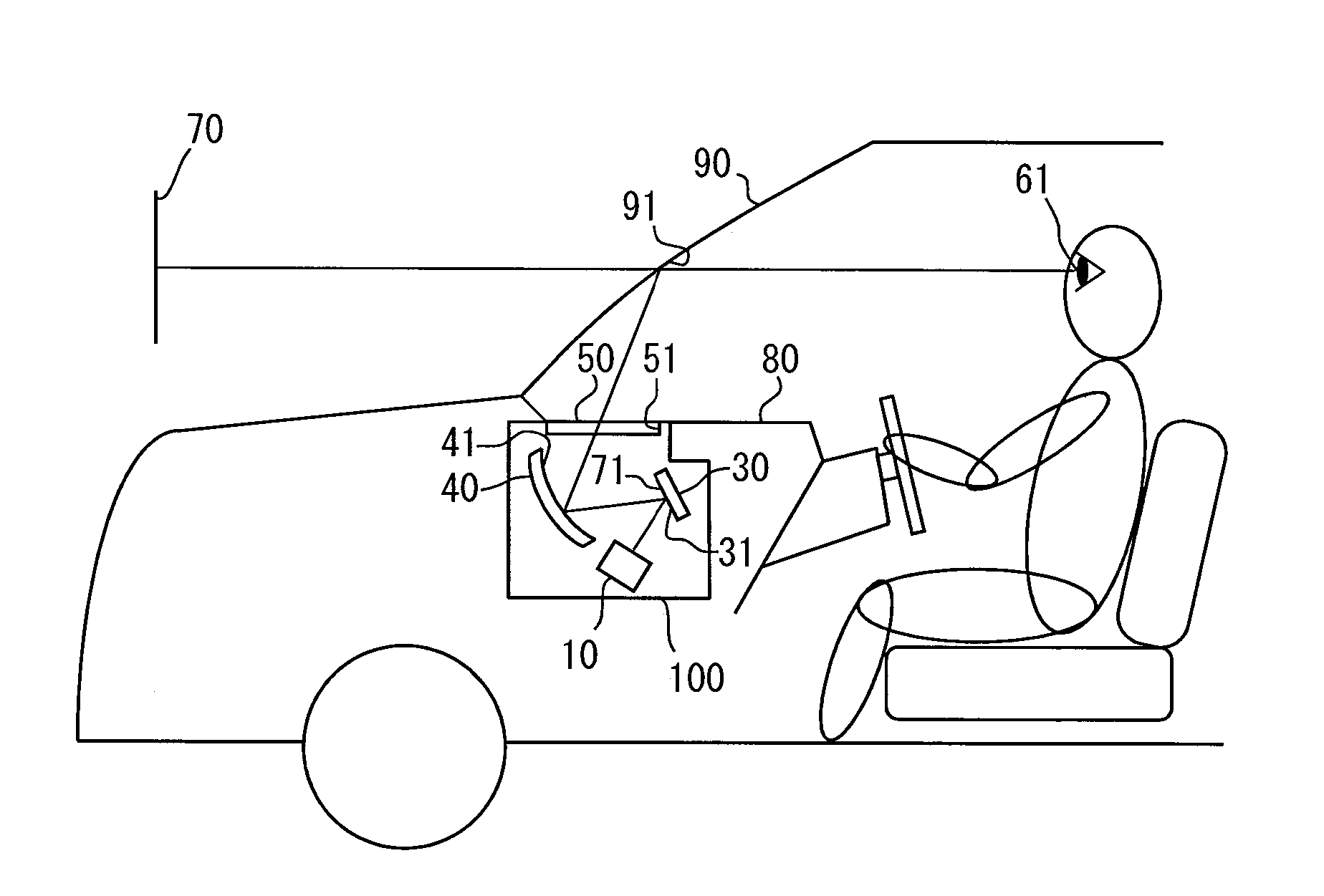
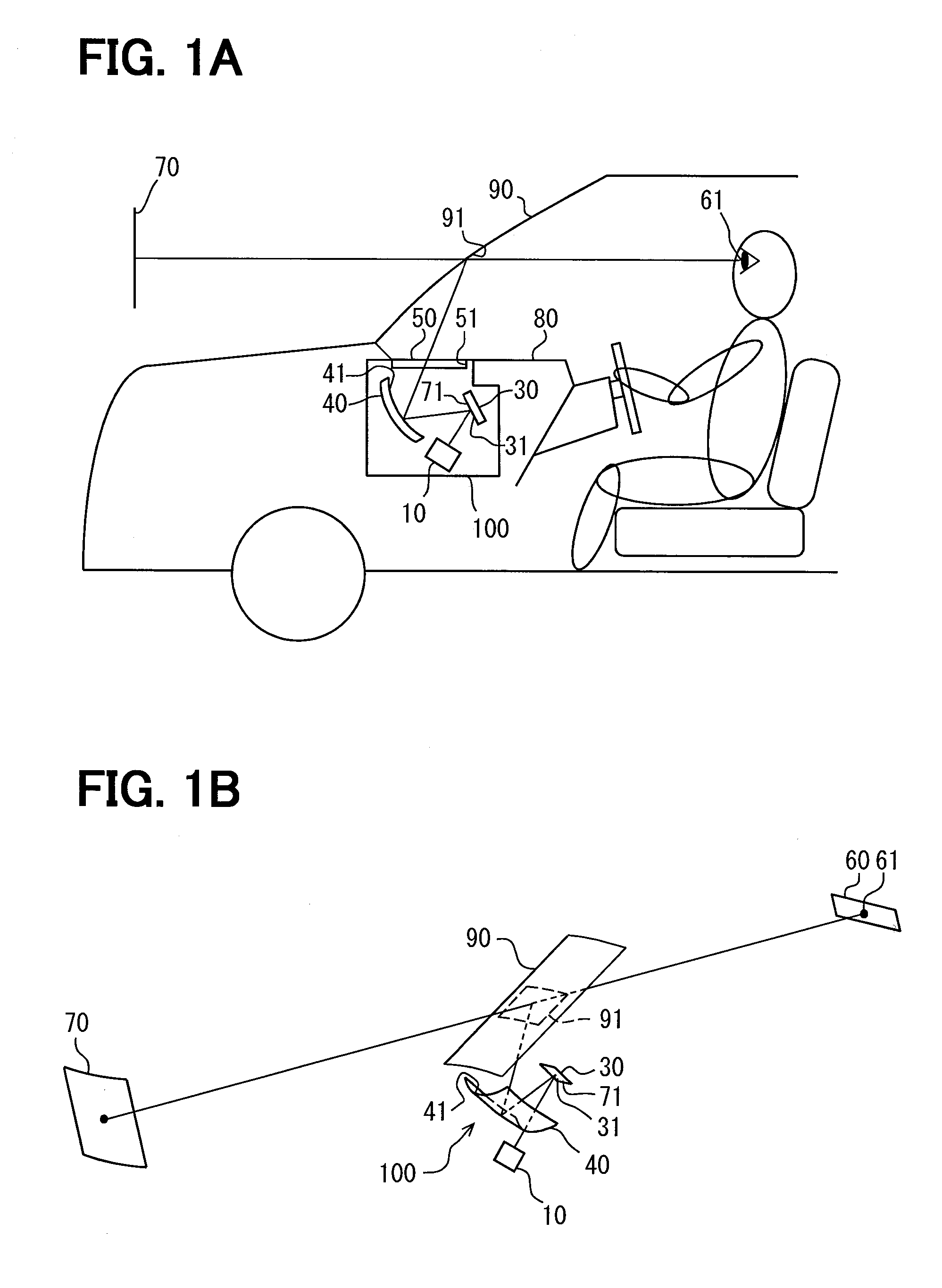
[0033]FIGS. 1A and 1B show a head-up display apparatus 100 according to a first embodiment of the present disclosure. The head-up display apparatus 100 is, for example, housed in an instrument panel of a vehicle. The head-up display apparatus 100 projects a display image 71, which has passed through a transparent dust-proof cover 50 covering an opening 51, onto a display member, such as a windshield 90 of a vehicle, so that a virtual image 70 of the display image 71 is able to be viewed from an assumed eye box 60. The eye box 60 is defined to a size in which a horizontal dimension thereof is approximately 100 to 200 millimeters and a vertical dimension thereof is approximately 40 to 90 millimeters. A projection surface 91 onto which the display image 71 is projected by the head-up display apparatus 100 is provided on an interior surface of the windshield 90 facing a passenger compartment of the vehicle. The projection surface 91 is curved into a concave shape...

second embodiment

[0067](Second Embodiment)

[0068]A second embodiment of the present disclosure as shown in FIGS. 17 and 18 is a modification of the first embodiment. A screen 230 of the second embodiment is a so-called hexagonal dense micromirror array. In the screen 230, micromirrors 234 include first micromirrors 235 (indicated only by an outline in FIG. 18), second micromirror 236 (indicated with dots in FIG. 18) and third micromirrors 237 (indicated with diagonal lines in FIG. 18).

[0069]The first to third micromirrors 235, 236 and 237 are repetitively arranged in a specific order in the y-axis direction. In other words, one first micromirror 235 is surrounded by the second micromirrors 236 and the third micromirrors 237, which are alternately arranged (see FIG. 18). Since the first to third micromirrors 235, 236, 237 are arranged in such an array, adjacent convex surface portions 232 have different curved shapes. In the second embodiment, the convex surface portions 232 have three different curve...

third embodiment

[0074](Third Embodiment)

[0075]A third embodiment of the present disclosure shown in FIG. 19 is a modification of the first embodiment. A screen 330 of the third embodiment has a shielding portion 339 between the first micromirrors 35 and the second micromirrors 36. The shielding portion 339 is made of a lightproof resin and is formed into a lattice shape. The shielding portion 339 covers the boundary 337 between the adjacent convex surface portions 32. The shielding portion 339 blocks the laser beam from transmitting. Therefore, the shielding portion 339 restricts reflection of the laser beam in the vicinity of the boundary 337. The shielding portion 339 may be formed by lightproof printing or the like. An area covered with the shielding portion 339 is preferably less than 10% of the area of the opening 38.

[0076]In the third embodiment described hereinabove, the boundary 337 between the convex surface portions 32, at which the shape of the scanned surface 31 possibly varies sharply,...


PUM


Abstract

A head-up display apparatus projects a display image onto a projection surface of a windshield so that a viewer views a virtual image of the display image from an eye box. A screen used in the apparatus is constructed of a plurality of micromirrors. Each micromirror has a convex surface portion being curved to magnify a laser beam toward the eye box. A scanned surface of the screen is provided by an array of the convex surface portions. In a cross section intersecting the scanned surface, adjacent convex surface portions have different curved shapes. Thus, brightness unevenness of the display image caused by interference of laser beams can be reduced while maintaining a simple structure of the screen such as a microlens array.

Description

CROSS REFERENCE TO RELATED APPLICATIONS[0001]This application is a U.S. National Phase Application under 35 U.S.C. 371 of International Application No. PCT / JP2013 / 003358 filed on May 28, 2013 and published in Japanese as WO 2013 / 179649 on Dec. 5, 2013. This application is based on and claims the benefit of priority from Japanese Patent Application No. 2012-123541 filed on May 30, 2012. The entire disclosures of all of the above applications are incorporated herein by reference.TECHNICAL FIELD[0002]The present disclosure relates to a screen member on which a display image is depicted by scanning a laser beam, and a head-up display apparatus using the screen member.BACKGROUND ART[0003]Conventionally, is has been known a head-up display apparatus that projects a display image onto a windshield or the like of a vehicle so that a virtual image of the display image can be viewed from an assumed viewing space. As a kind of such apparatus, for example, a patent literature 1 discloses a scan...

Claims


Application Information

Patent Timeline
Patent Type & Authority Patents(United States)
IPC IPC(8): G02B27/14G02B27/01G02B27/48G02B3/00G02B26/10
CPCG02B27/0101G02B27/48G02B3/0043G02B3/0056G02B26/10G02B2027/0118
Inventor ANDO, HIROSHIFUJIKAWA, TAKAYUKI
Owner DENSO CORP
Why Eureka
Try Eureka