
System and method for imaging through an irregular water surface

a technology of irregular water surface and imaging system, applied in the field of imaging, can solve the problems of unintelligible raw imagery collected by such a camera, and cannot see as far as a conventional periscope extended above the wave tops

Inactive Publication Date: 2009-12-08
UNIV OF MASSACHUSETTS
View PDF5 Cites 12 Cited by
  • Summary
  • Abstract
  • Description
  • Claims
  • Application Information

AI Technical Summary

Benefits of technology

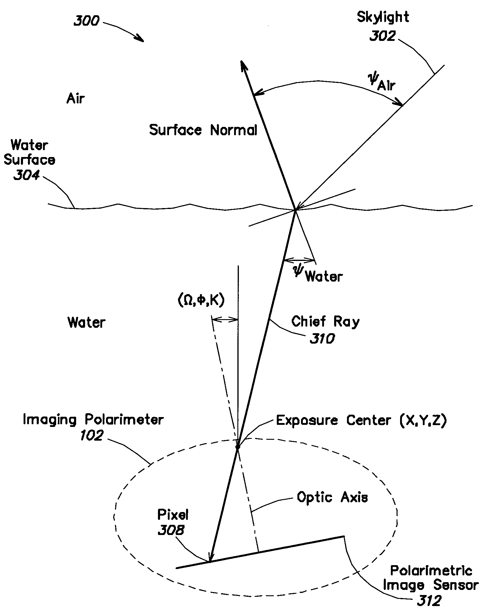
The present invention is an underwater imaging system that uses polarimetric data to capture images of the water surface. This technique is different from conventional optical remote sensing techniques that rely on light amplitude and frequency. The system measures the polarization properties of the reflected and / or refracted light to determine the orientation of the surface. This allows for the recovery of the two-dimensional slope field of a short gravity wave without interfering with the fluid dynamics of the air or water. The invention is advantageous in that it utilizes the physics of light scattering by a specular surface and measures the polarization properties of the reflected and / or refracted light. The orientation of the surface can be computed in each pixel's field-of-view.

Problems solved by technology

Because the underwater imaging system disclosed in this patent relies on peaked waves to collect rays from near the horizon, it cannot see as far as a conventional periscope extended above the wave tops.
However, the raw imagery collected by such a camera is unintelligible due to the distorting influence of waves on the ocean surface.

Method used


Image

  • System and method for imaging through an irregular water surface
  • System and method for imaging through an irregular water surface
  • System and method for imaging through an irregular water surface

Examples


Embodiment Construction

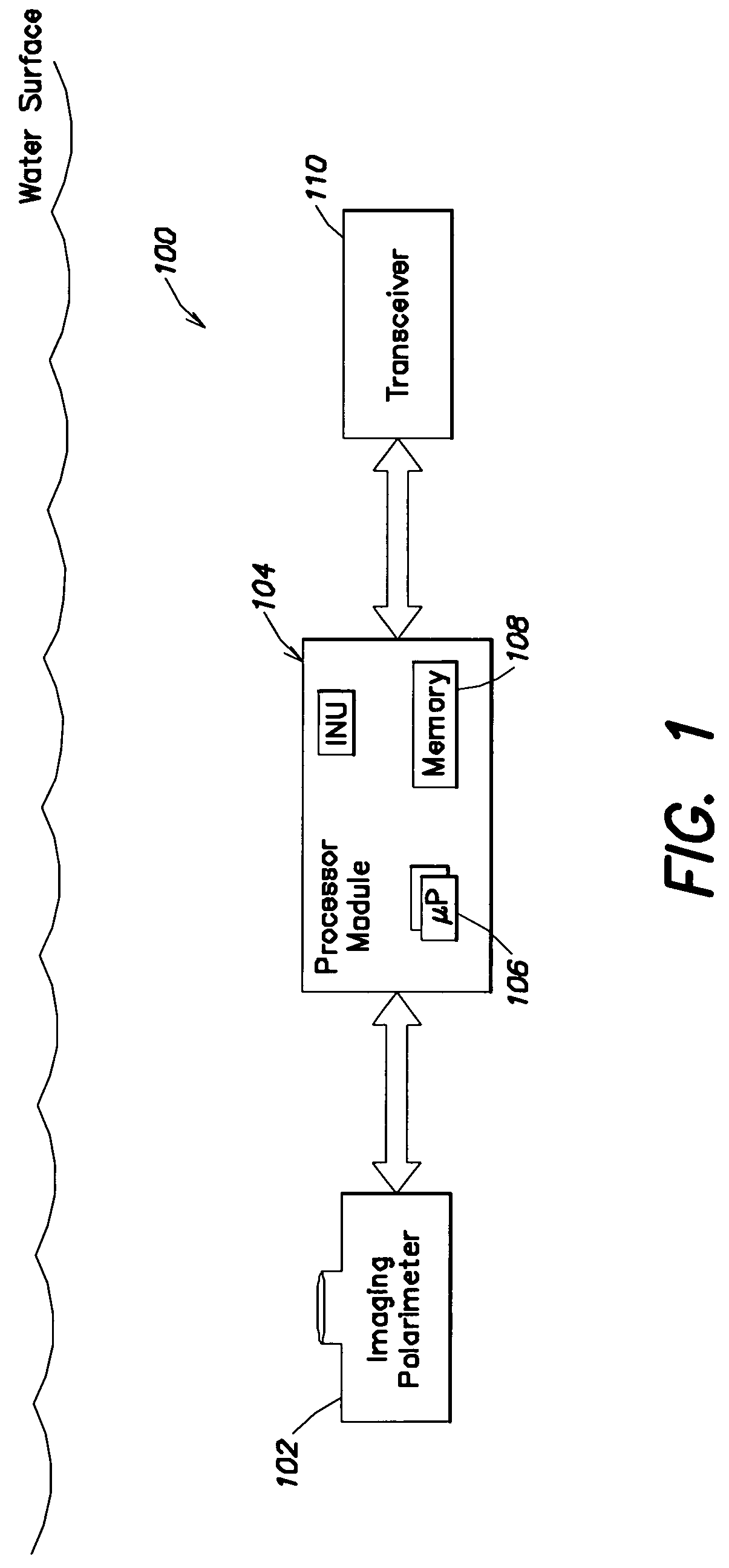
[0018]FIG. 1 is a pictorial illustration of an underwater imaging system 100 that includes an imaging polarimeter 102 located beneath the surface of the water. The system also includes a processor module 104 comprising a processor 106 (e.g., one or more DSPs) and memory 108. The system may also include a transceiver 110 that allows the system 100 to communicate with devices above and possibly also underneath the surface of the water. An image storage device may also be included with the system.

[0019]The imaging polarimeter system provides four data components, where the four components are equivalent to the I,Q,U,V elements of the Stokes vector. An imaging polarimeter is similar to a three-component R,G,B color camera, except that four components of polarization are measured instead of three components of color. The underwater imaging polarimeter may be characterized by several requirements. First, the underwater imaging polarimeter should have an integration time fast enough to fre...


PUM


Abstract

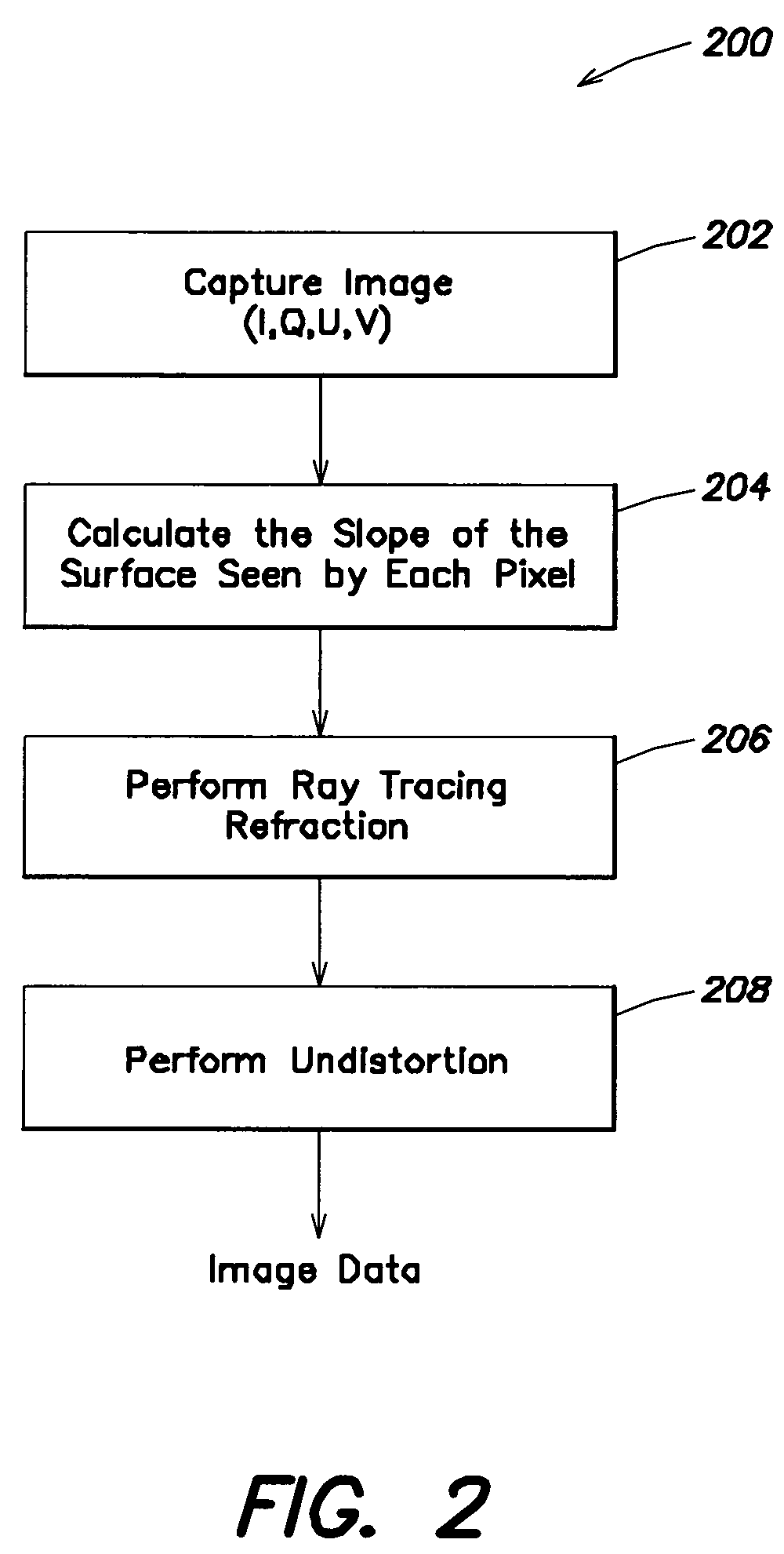
An underwater imaging system includes an underwater imaging polarimeter that captures images of the water surface. The captured images are indicative of the captured light, and are equivalent to four-component Stokes vector S=(I,Q,U,V) data. Advantageously, the passive imaging technique of the present invention utilizes polarmetric data. In contrast, conventional optical remote sensing techniques rely on light amplitude and frequency to carry information about the scattering surface. The imaging technique of the present invention exploits these properties, as well as the polarization properties of light to sense information about the scattering media. The two-dimensional slope field of surface wave can be recovered from a distance without interfering with the fluid dynamics of the air or water. By employing the physics of light scattering by a specular surface, the geometry of the surface can be found by measuring the polarimetric properties of the reflected and / or refracted light. The derived two-dimensional slope field in then used to remove the image distortion caused by light passing through the wavy surface. The undistorted images have the appearance of images taken through a flat water surface.

Description

PRIORITY INFORMATION[0001]This patent application claims priority from U.S. provisional patent application Ser. No. 60 / 851,487 filed Oct. 13, 2006 and U.S. provisional patent application Ser. No. 60 / 883,284 filed Jan. 3, 2007, both applications are hereby incorporated by reference.BACKGROUND OF THE INVENTION[0002]The present invention relates to the field of imaging, and in particular to forming an image of the above surface environment located on or above the surface of the water from underneath the water utilizing an imaging polarimeter to infer the two-dimensional slope of the water surface in the field-of-view of the image pixels.[0003]U.S. Pat. No. 5,528,493 entitled Virtual Periscope discloses the use of an underwater camera, processor, and display system that reconstructs a fragmented image seen from below the surface into a view of the hemisphere atop the ocean surface. Unlike a conventional periscope that collects light from a position above the ocean surface, this U.S. pat...

Claims


Application Information

Patent Timeline
Patent Type & Authority Patents(United States)
IPC IPC(8): G01J4/00
CPCG01J4/04
Inventor SCHULTZ, HOWARDCORRADA-EMMANUEL, ANDRES
Owner UNIV OF MASSACHUSETTS
Learn More