Retaining clip for reagent test slides

a technology for reagent test slides and clips, which is applied in the field of holding and storage devices to achieve the effect of reducing the contamination of slides

Active Publication Date: 2009-12-15
IDEXX LABORATORIES +1
View PDF67 Cites 10 Cited by
  • Summary
  • Abstract
  • Description
  • Claims
  • Application Information

AI Technical Summary

Benefits of technology

[0009]It is a further object of the present invention to provide a retaining clip which is adaptable for holding one or more test slides in a stacked arrangement.
[0010]It is still another object of the present invention to provide a retaining clip for holding a plurality of test slides which avoids the need for the user to handle the edges of the test slides when inserting them into a chemical analyzer.
[0011]It is yet a further object of the present invention to provide a retaining clip for a plurality of test slides which minimize the contamination of the slides from the environment or other sources.
[0013]In another embodiment of the present invention, the retaining clip includes a middle plate having opposite first and second sides and a slot formed through the thickness thereof, a first cover plate extending outwardly from the first side of the middle plate and which preferably has an extended portion that passes through the slot of the middle plate, and a second cover plate which is joined to the middle plate and extends outwardly from the first side of the middle plate. The first cover plate and the second cover plate are in overlying relationship with each other to define therebetween a space for receiving the plurality of reagent test slides in a stacked arrangement. Preferably, the retaining clip includes a foldable handle extending from the second side of the middle plate. When folded, the handle partially overlies the surface of the second side of the middle plate to provide the retaining clip with a compact size for shipping or when not being handled.
[0015]Alternatively, the retaining clip just previously described may be modified such that the middle plate may further include undulations which define at least one recess formed in the first side of the middle plate and extending toward the second side and in a direction between the first cover plate and the second cover plate, and at least one projecting guide structure extending outwardly toward the space for receiving the plurality of reagent test slides and in a direction between the first cover plate and the second cover plate. Also, the first cover plate may be modified from the just previously described embodiment to further include at least one tab which is slidably received by the at least one recess of the middle plate. The first cover plate also includes an exposed edge facing the middle plate and at least one recess formed in the exposed edge. The at least one projecting guide structure of the middle plate is slidably received by the at least one recess of the first cover plate. Accordingly, the at least one tab and the at least one recess of the first cover plate cooperate respectively with the at least one projecting guide structure and the at least one recess of the middle plate to minimize lateral movement of the first cover plate with respect to the middle plate. Again, of course, the positions of the cooperating recesses, tab and guide structure on the middle plate and first cover plate may be reversed.

Problems solved by technology

Additionally, once the test slide is removed from its sealed container, it should be used or otherwise loaded immediately in the chemical analyzer, as the analyte on the film portion of the test slide is now exposed to contaminants in the environment which may corrupt the tests performed by the chemical analyzer.

Method used


Image

  • Retaining clip for reagent test slides
  • Retaining clip for reagent test slides
  • Retaining clip for reagent test slides

Examples


first embodiment

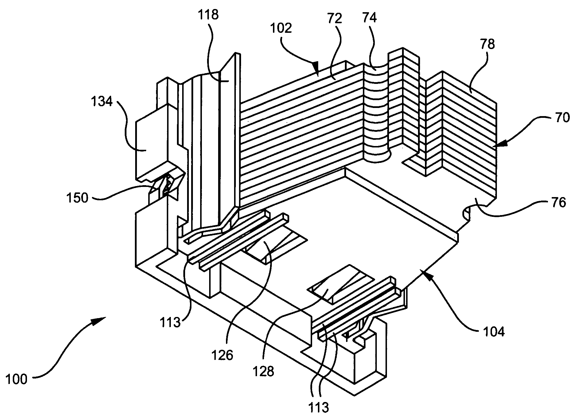
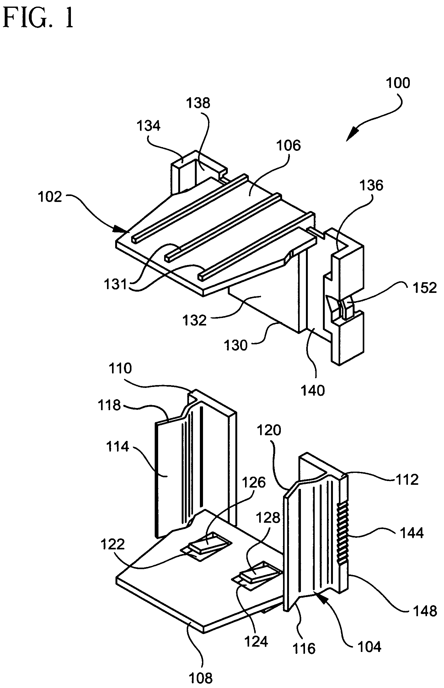
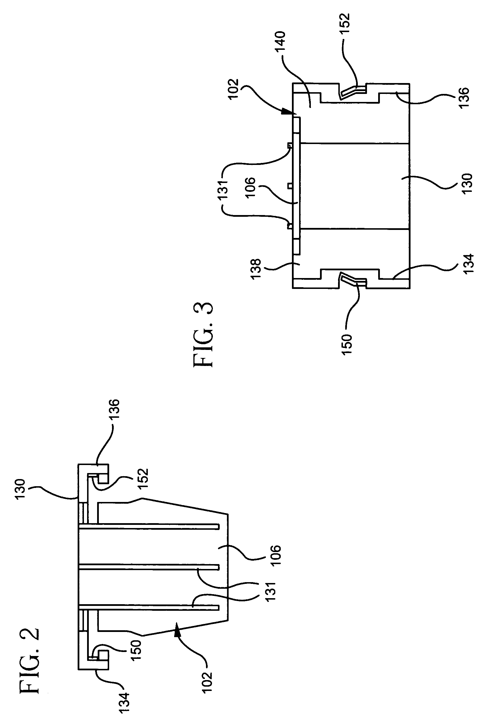
[0068]a retaining clip 100 formed in accordance with the present invention is illustrated by FIGS. 1-16 of the drawings. The retaining clip 100 of this particular embodiment includes a top cover assembly 102 and a bottom cover assembly 104. The top cover assembly 102 includes a top cover plate (also referred to herein as “first cover plate”) 106, and the bottom cover assembly 104 includes a bottom cover plate (also referred to herein as “second cover plate”) 108. The top cover plate 106 and the bottom cover plate 108 define between them a space for receiving a plurality of reagent test slides.

[0069]The bottom cover assembly 104 includes the bottom cover plate 108, as mentioned previously, and a first rail 110 and a second rail 112 extending parallelly in the same direction from, and affixed to, the bottom cover plate 108. Each of the first and second rails 110 and 112 are plate-like in formation, and includes free standing, resilient members 114 and 116 biased inwardly toward one an...

second embodiment

[0080]The retaining clip 200 of the second embodiment further includes a top cover plate (also referred to herein as “first cover plate”) 212 which is slidably mounted on the back wall 204. More specifically, the top cover plate 212 includes a generally planar main body portion 214, and a T-shaped extension 216 which extends from its rear edge 218 of the main body portion 214. The T-shaped extension 216 includes a narrow portion 227 extending outwardly from the main body portion 214, and a widened portion 226 joined to the end of the narrow portion 227. This T-shaped extension 216 is slidingly received by a slot 225 formed preferably centrally through the thickness of the back wall 204 and extends at least partially longitudinally along the back wall 204 between the bottom cover plate 202 and the top edge 203 of the back wall 204. The slot 225 in the back wall 204 is particularly dimensioned to have a width W3 which is equal to or slightly greater than the width W4 of the narrower p...

third embodiment

[0094]As in the previous embodiment illustrated by FIGS. 17-22, the third embodiment illustrated by FIGS. 23-28 includes a handle 354 for grasping by the user. The handle 354 extends outwardly and preferably perpendicularly from the rear surface 355 of the back wall 304 and is connected to the rear surface 355 through a bi-directional living hinge 356. Unlike the previous embodiment illustrated by FIGS. 17-20, in this particular embodiment, the bi-directional living hinge 356 is used to mount the handle 354 to the back wall 304 and to allow the handle 354 to be moved from its outwardly extended position to a folded, unextended position against or in close proximity to the rear surface 355 of the back wall 304 in the direction of either one lateral side wall 306 or the other lateral side wall 308.

[0095]Preferably, the handle 354 is T-shaped in longitudinal cross-section, and is formed with an extended portion 358 which is joined to the living hinge 356, and a transverse section 360 m...


PUM

PropertyMeasurementUnit
angleaaaaaaaaaa
thicknessaaaaaaaaaa
lengthaaaaaaaaaa

Abstract

A retaining clip for retaining reagent test slides in a stacked arrangement includes a first assembly having a first cover plate and at least two parallel, co-planar rails extending transversely from an inner surface of the first cover plate. A second assembly includes a second cover plate, and a rail receiving platform extending transversely from an inner surface of the second cover plate. The first cover plate and the second cover plate define between them a space for receiving the plurality of reagent test slides. The rails of the first assembly include ratchet teeth, and the rail receiving platform of the second assembly includes pawls. The pawls engage the ratchet teeth to prevent the separation of the first assembly and the second assembly and to securely but removably hold the plurality of reagent test slides in a stacked arrangement between the first and second cover plates.

Description

CROSS-REFERENCE TO RELATED APPLICATIONS[0001]This application is related to U.S. provisional patent application Ser. No. 60 / 526,885, filed on Dec. 4, 2003, and entitled “Retaining Clip For Reagent Test Slides”, and to U.S. provisional patent application Ser. No. 60 / 526,884, filed on Dec. 4, 2003, and entitled “Reagent Test Slide Injector Mechanism Having a Scotch Drive and Rotatable Turntable Having a Geneva Drive for a Chemical Analyzer”, the disclosure of each of which is incorporated herein by reference. This application claims benefit of priority under 35 U.S.C. §119 to the aforementioned related provisional applications.BACKGROUND OF THE INVENTION[0002]1. Field of the Invention[0003]The present invention relates to chemical analyzers using dry chemistry reagent test slides, and more particularly relates to holding and storage devices for such reagent test slides prior to use and upon insertion of the test slides in a chemical analyzer.[0004]2. Description of the Prior Art[0005]...

Claims


Application Information

Patent Timeline
Patent Type & Authority Patents(United States)
IPC IPC(8): B01L3/00G01N21/00B01L9/00G01N31/00G01N33/543G01N35/00
CPCB01L9/52G01N35/00029G01N33/54386B01L2200/025B01L2300/0822G01N2035/00138G01N2035/00039G01N2035/00089
Inventor BARSKI, STANISLAWCHIAPPERI, JOSEPH MICHAELDEACON, MARK ELLIOTTDUMONT, MARK R.PIERSON, MARK WESTONKEEGAN, TIMOTHY ROBERTLOESER, MARK BENNOMEILER, GERALD GEORGEGOLDMAN, ROSS BRYANRICH, CARL RUSSELLVERSLUYS, RICHARD JAMES
Owner IDEXX LABORATORIES
Why Eureka
Try Eureka