Door lock apparatus

a door lock and door lock technology, applied in the field of door lock apparatuses, can solve the problems of door lock apparatus trouble, short circuit of electric parts, and insufficient work of third covers

Active Publication Date: 2009-12-29
AISIN SEIKI KK
View PDF21 Cites 18 Cited by
  • Summary
  • Abstract
  • Description
  • Claims
  • Application Information

AI Technical Summary

Benefits of technology

[0007]According to an aspect of the present invention, a door lock apparatus includes a housing for accommodating a latch mechanism for holding a vehicle door to a vehicle body in a closed state, a lever mechanism actuated when a door handle provided inside or outside the vehicle door is operated, a link mechanism provided between the lever mechanism and the latch mechanism for connecting the lever mechanism to the latch mechanism, the link mechanism having a first position for transmitting operational force from the lever mechanism to the latch mechanism and a second position for preventing transmission of the operational force from the lever mechanism to the latch mechanism, and a motor drive mechanism for changing the first and second positions of the link mechanism. The housing includes a first accommodating space for accommodating the motor drive mechanism and a second accommodating space adjacently provided to the first accommodating space for accommodating the latch mechanism and a water preventing means is provided for preventing water from entering the first accommodating space from outside the housing.

Problems solved by technology

In these mechanisms, because the motor drive mechanism is configured from an electric part, if the motor drive mechanism makes contact with water, the electric part will be short-circuited and the short will cause trouble.
In this case, the third cover cannot sufficiently work any more.
Then, there can be a danger that water enters the housing through the joint portion of the first cover and the second cover and induces short-circuit of the electric part, or induces other adverse effects, and causes trouble of the door lock apparatus.

Method used


Image

  • Door lock apparatus
  • Door lock apparatus
  • Door lock apparatus

Examples


Embodiment Construction

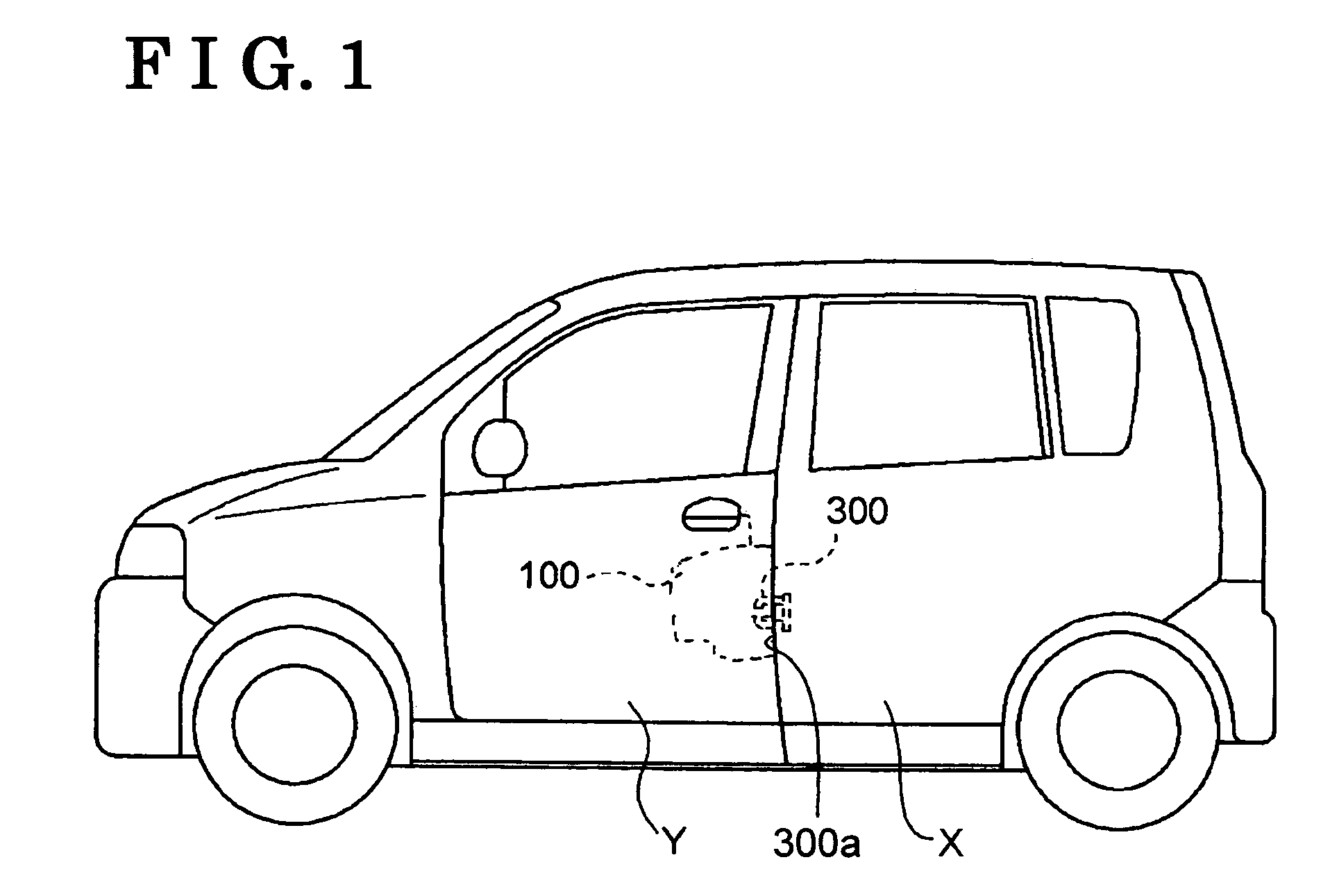
[0016]An embodiment of the present invention will be explained with reference to drawing figures. FIG. 1 represents a schematic diagram illustrating a door lock apparatus 100 according to the embodiment of the present invention. In FIG. 1, the door lock apparatus 100 is installed in a vehicle door Y. The door lock apparatus 100 is installed so as to face a striker 300 provided at a vehicle body X when the vehicle door Y is closed. A type of the vehicle door Y is not particularly limited. The vehicle door Y can be a hinge type door, a sliding door, or the like. Further, in FIG. 1, the door lock apparatus 100 is installed in a side door, serving as the vehicle door Y, for an occupant to get on and off a vehicle. However, it is not limited. The door lock apparatus 100 can be installed in a trunk lid of a hatchback.

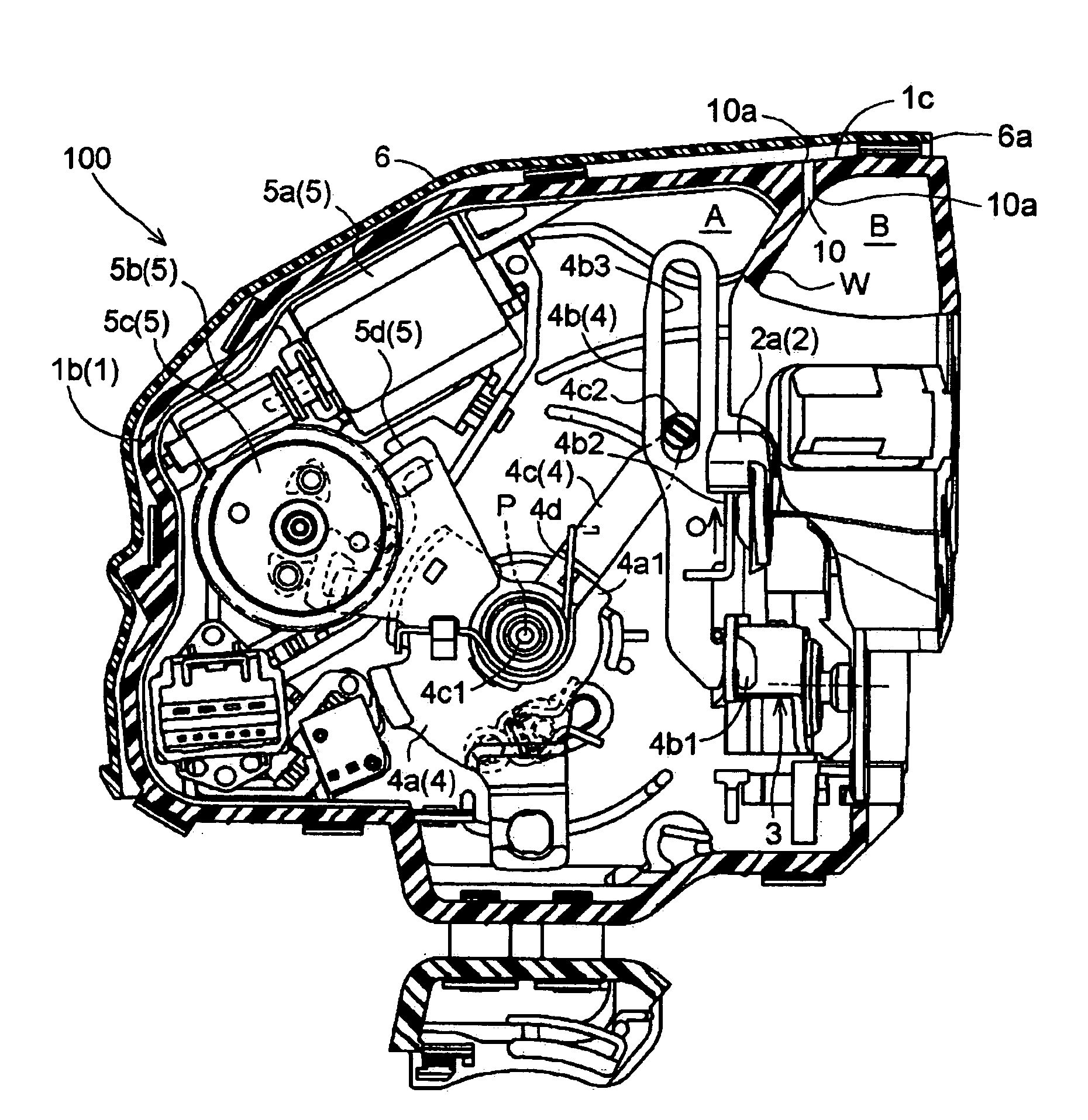
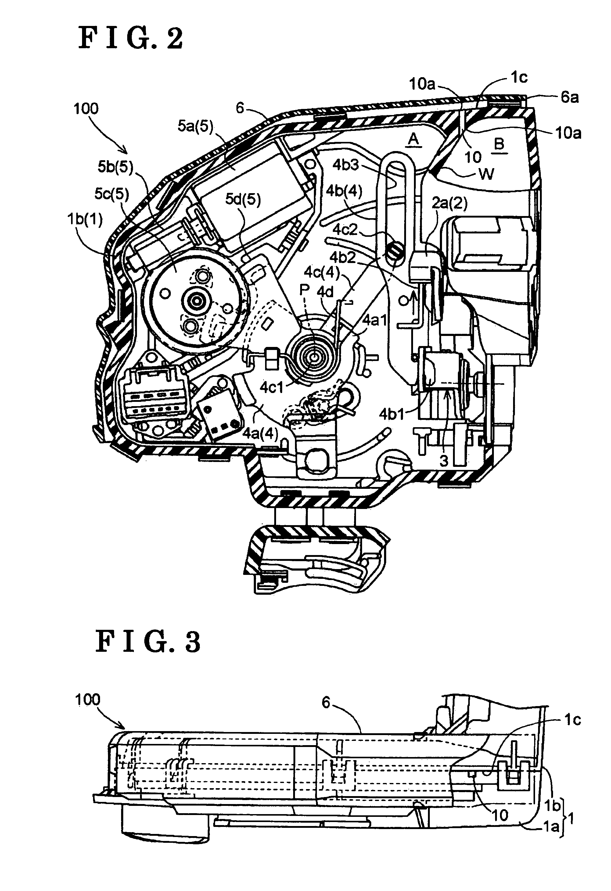
[0017]Structure of the door lock apparatus 100 will be explained. FIG. 2 represents a front view illustrating inner structure of the door lock apparatus 100 according to the ...


PUM


Abstract

A door lock apparatus includes a housing for accommodating a latch mechanism for holding a vehicle door to a vehicle body, a lever mechanism actuated when a door handle is operated, a link mechanism for connecting the lever mechanism to the latch mechanism, the link mechanism having a first position for transmitting operational force from the lever mechanism to the latch mechanism and a second position for preventing transmission of the operational force from the lever mechanism to the latch mechanism, and a motor drive mechanism for changing the first and second positions of the link mechanism. The housing includes a first accommodating space for accommodating the motor drive mechanism and a second accommodating space adjacently provided to the first accommodating space for accommodating the latch mechanism and a water preventing portion is provided for preventing water from entering the first accommodating space from outside the housing.

Description

CROSS REFERENCE TO RELATED APPLICATIONS[0001]This application is based on and claims priority under 35 U.S.C. §119 to Japanese Patent Application 2005-047497, filed on Feb. 23, 2005 and Japanese Patent Application 2005-089427, filed on Mar. 25, 2005, the entire content of which is incorporated herein by reference.FIELD OF THE INVENTION[0002]This invention generally relates to a door lock apparatus. More specifically, this invention pertains to a door lock apparatus applicable to a vehicle, or the like.BACKGROUND[0003]Conventionally, a door lock apparatus includes a latch mechanism, a lever mechanism, a link mechanism, and a motor drive mechanism, or the like, provided in a housing (as disclosed in JP2003-314116A; document 1). The latch mechanism changes a state of the vehicle door to the vehicle body between a state where the vehicle door is retained to be closed and a state where the vehicle door is enabled to open. The lever mechanism is actuated when a door opening means such as ...

Claims


Application Information

Patent Timeline
Patent Type & Authority Patents(United States)
IPC IPC(8): E05C3/16
CPCE05B77/34E05B85/02Y10S292/23Y10T292/1047Y10T292/1082
Inventor SUZUMURA, MAKOTOMURAMATSU, AKIRATANABE, SIGERUKUNIMATSU, YUKINOBU
Owner AISIN SEIKI KK
Why Eureka
Try Eureka