Plasma-disc article of manufacture

a technology of plasma discs and manufacture articles, which is applied in the direction of discharge tubes/lamp details, discharge tubes luminescnet screens, gas-filled discharge tubes, etc., can solve the problems of shortening the life of phosphor and pdp

Inactive Publication Date: 2009-12-29
IMAGING SYST TECH
View PDF214 Cites 17 Cited by
  • Summary
  • Abstract
  • Description
  • Claims
  • Application Information

AI Technical Summary

Benefits of technology

[0059]Farnand 194 discloses a similar process comprising polymers dissolved in naphthalene including polyethylene and polystyrene. The core is sublimed or evaporated to form hollow spheres or microballoons. Kobayashi et al. 689 discloses the coating of a core of polystyrene with carbon powder. The core is heated and decomposed and the carbon powder heated in argon at 3000° C. to obtain hollow porous graphitized spheres. Genes 738 discloses the making of lightweight aggregate using a nucleus of expanded polystyrene pellet with outer layers of sand and cement. Sargeant et al. 051 discloses the making of light weight-refractories by wet spraying core particles of polystyrene with an aqueous refractory coating such as clay with alumina, magnesia, and / or other oxides. The core particles are subject to a tumbling action during the wet spraying and fired at 1730° C. to form porous refractory. Duperray et al. 821 discloses the making of a porous metal body by suspending metal powder in an organic foam which is heated to pyrolyze the organic and sinter the metal. Jaeckel 598 and Jaeckel et al. 857 disclose the coating of a polymer core particle such as foamed polystyrene with metals or inorganic materials followed by pyrolysis on the polymer and sintering of the inorganic materials to form the sphere. Both disclose the making of metal spheres such as copper or nickel spheres which may be coated with an oxide such as aluminum oxide. Jaeckel et al. 857 further discloses a fluid bed process to coat the core.

Problems solved by technology

The discharge between the two opposite electrodes generates electrons and ions that bombard and deteriorate the phosphor thereby shortening the life of the phosphor and the PDP.

Method used


Image

  • Plasma-disc article of manufacture
  • Plasma-disc article of manufacture
  • Plasma-disc article of manufacture

Examples


Embodiment Construction

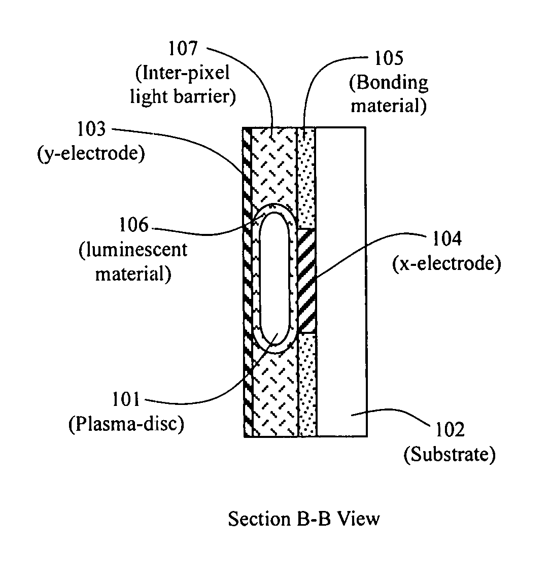
[0140]In accordance with this invention, at least two conductors or electrodes are electrically connected to a Plasma-disc in contact with a substrate. In one embodiment, the electrodes are connected to the Plasma-disc by means of an electrically conductive bonding substance applied to each Plasma-disc and / or to the electrode and / or to both the Plasma-disc and the electrode. In another embodiment, each electrically conductive bonding substance connection to each Plasma-disc is separated from each other electrically conductive bonding substance connection on the Plasma-disc by an insulating barrier so as to prevent the conductive substance forming one electrical connection from flowing and electrically shorting out another electrical connection.

DETAILED DESCRIPTION OF DRAWINGS

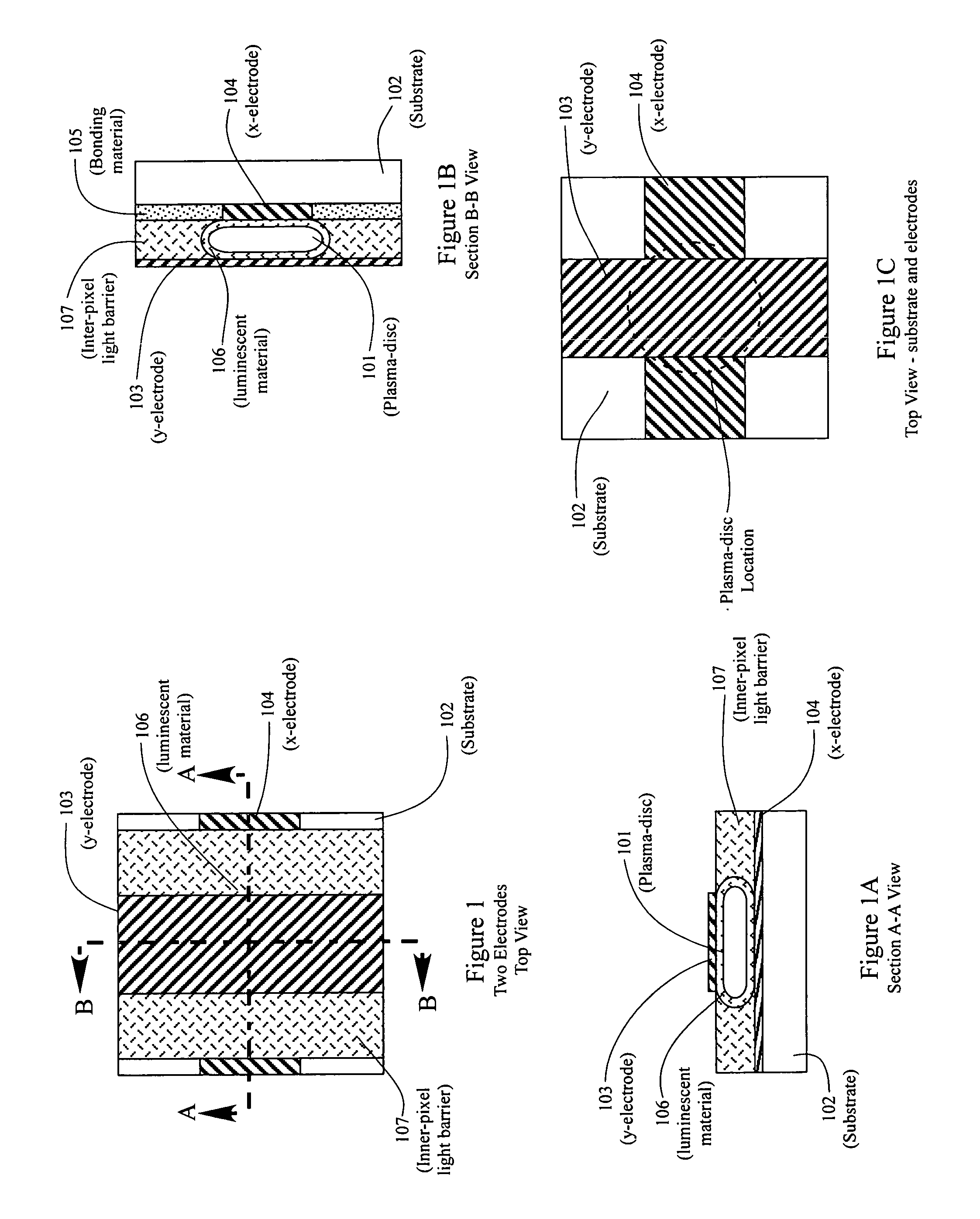
[0141]FIG. 1 shows substrate 102 with transparent y-electrode 103, luminescent material 106, x-electrode 104, and inner-pixel light barrier 107. The y-electrode 103 and x-electrode 104 are cross-hatched for iden...


PUM


Abstract

There is disclosed an article of manufacture comprising a Plasma-Disc™ for use in a plasma display panel (PDP) device having one or more substrates and a multiplicity of pixels or sub-pixels. Each pixel or sub-pixel is defined by a hollow Plasma-Disc™ filled with an ionizable gas. The Plasma-disc has at least two opposing flat sides such as a flat top and flat bottom or a flat rear and flat front. One or more other sides or edges may also be flat. Two or more electrodes are in electrical contact with each Plasma-disc. A flat base side of the Plasma-disc shell is in contact with a substrate and each electrode is in electrical contact with a flat side of the Plasma-disc. The PDP may also include inorganic and organic luminescent materials that are excited by the gas discharge within each Plasma-disc. The luminescent material may be located on an exterior and/or interior surface of the Plasma-disc or incorporated into the shell of the Plasma-disc. Up-conversion and down-conversion materials may be used. The substrate may be rigid or flexible with a flat, curved, or irregular surface.

Description

RELATED APPLICATIONS[0001]Priority is claimed under 35 U.S.C. 119(e) for Provisional Application Ser. No. 60 / 648,386, filed Feb. 1, 2005. This application is also a continuation-in-part under 35 USC 120 of U.S. patent application Ser. No. 10 / 431,446, filed May 8, 2003, now U.S. Pat. No. 7,456,571 issued Nov. 25, 2008, which claims priority under 35 USC 119(e) of Provisional Application Ser. No. 60 / 381,822, filed May 21, 2002.FIELD OF THE INVENTION[0002]This invention relates to an article of manufacture comprising a Plasma shell for use in a plasma display panel (PDP). This invention particularly relates to a Plasma-disc to be positioned in contact with a PDP substrate and electrically connected to electrical conductors such as electrodes. The hollow Plasma-discs are filled with an ionizable gas and are used as pixels or subpixels in a gas discharge plasma display panel (PDP) device. A Plasma-disc has at least two opposing flat sides such as a flattened top and bottom. Other sides o...

Claims


Application Information

Patent Timeline
Patent Type & Authority Patents(United States)
IPC IPC(8): H01J17/49
CPCH01J11/22H01J11/18
Inventor WEDDING, DANIEL K.WEDDING, CAROL ANNSTRBIK, III, OLIVER M.
Owner IMAGING SYST TECH
Why Eureka
Try Eureka