Active headrest of a vehicle that rotates horizontally and moves laterally based on angle and direction of inertia force caused by rear-impact

a technology of active headrest and rear-impact angle, which is applied in the direction of chairs, pedestrian/occupant safety arrangements, instruments, etc., can solve the problem of not taking into account the direction of an inertial force applied to the passenger's head

Inactive Publication Date: 2009-12-29
TOYOTA JIDOSHA KK
View PDF23 Cites 55 Cited by
  • Summary
  • Abstract
  • Description
  • Claims
  • Application Information

AI Technical Summary

Problems solved by technology

However, the direction of an inertia force applied to the passenger's head at the time of an actual rear-end collision is not always the rearward direction which is parallel to the longitudinal axial direction of the vehicle.
Nevertheless, such variation in the direction of an inertial force applied to the passenger's head is not taken into account in the configuration of the headrest apparatus described in JP-A-2003-191778.

Method used


Image

  • Active headrest of a vehicle that rotates horizontally and moves laterally based on angle and direction of inertia force caused by rear-impact
  • Active headrest of a vehicle that rotates horizontally and moves laterally based on angle and direction of inertia force caused by rear-impact
  • Active headrest of a vehicle that rotates horizontally and moves laterally based on angle and direction of inertia force caused by rear-impact

Examples


Embodiment Construction

[0025]Hereafter, an embodiment of the invention will be described with reference to the accompanying drawings.

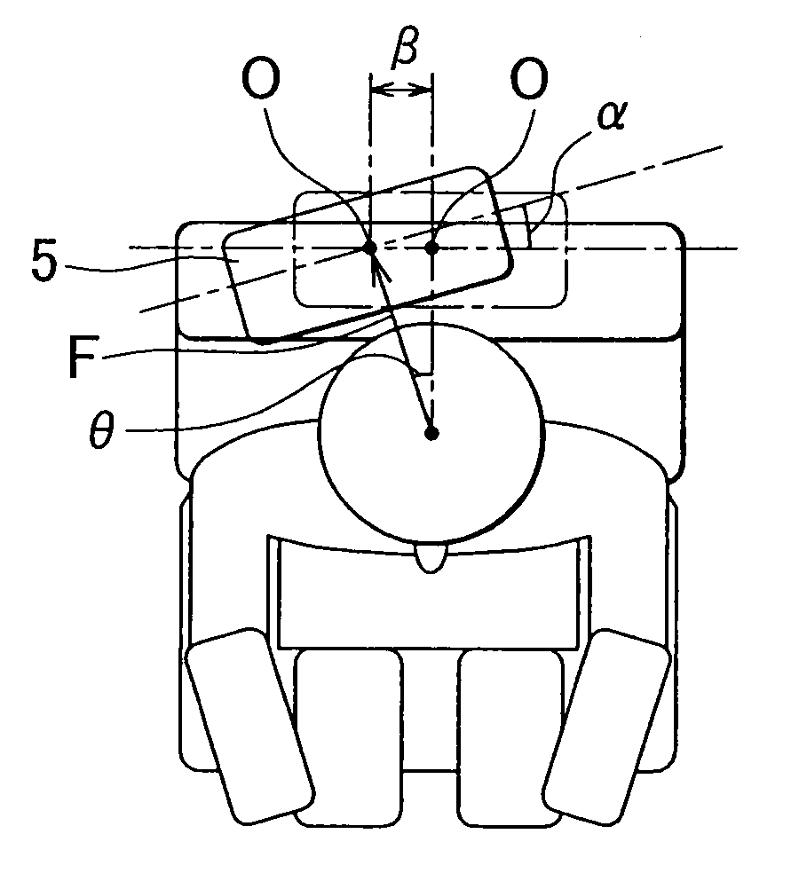
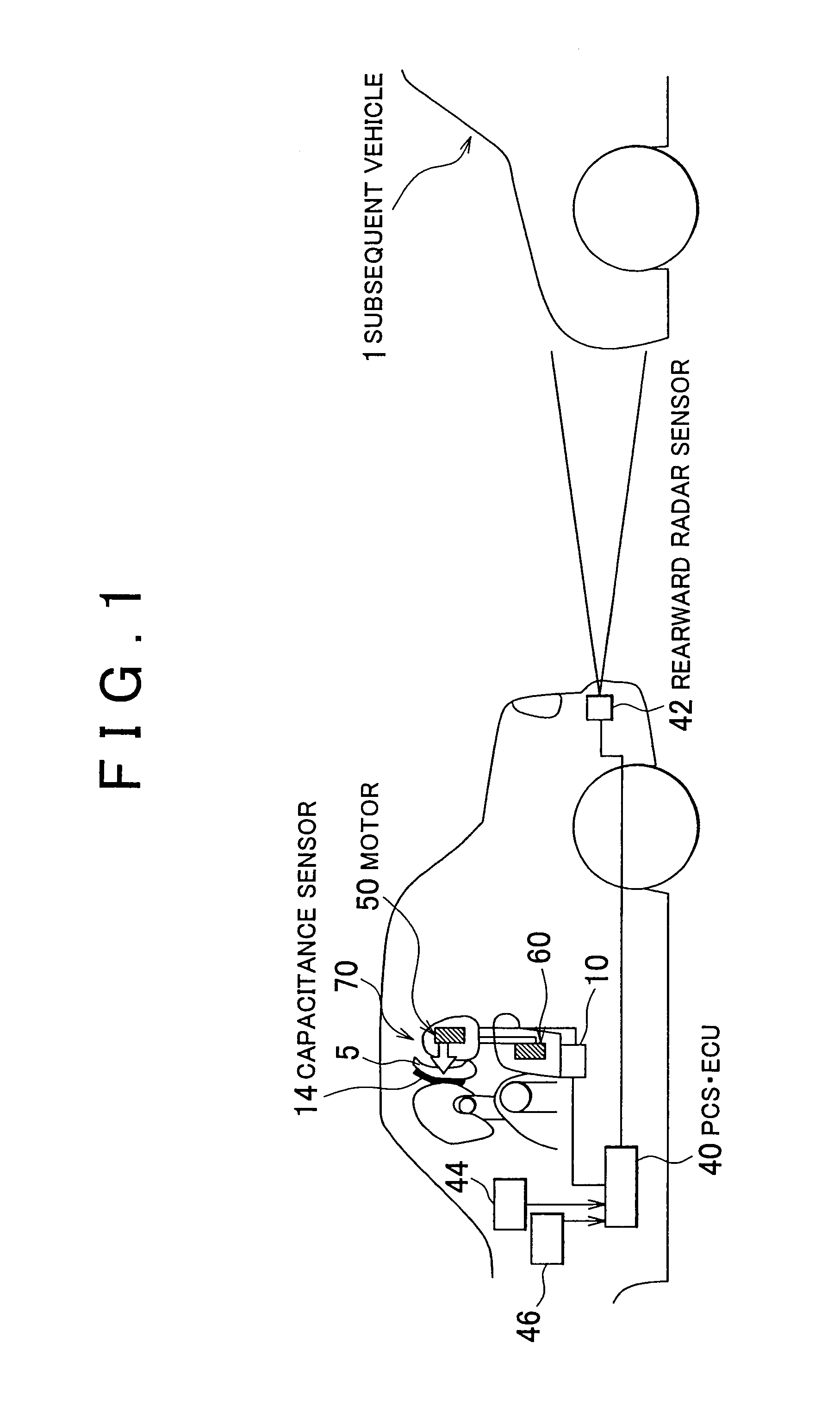
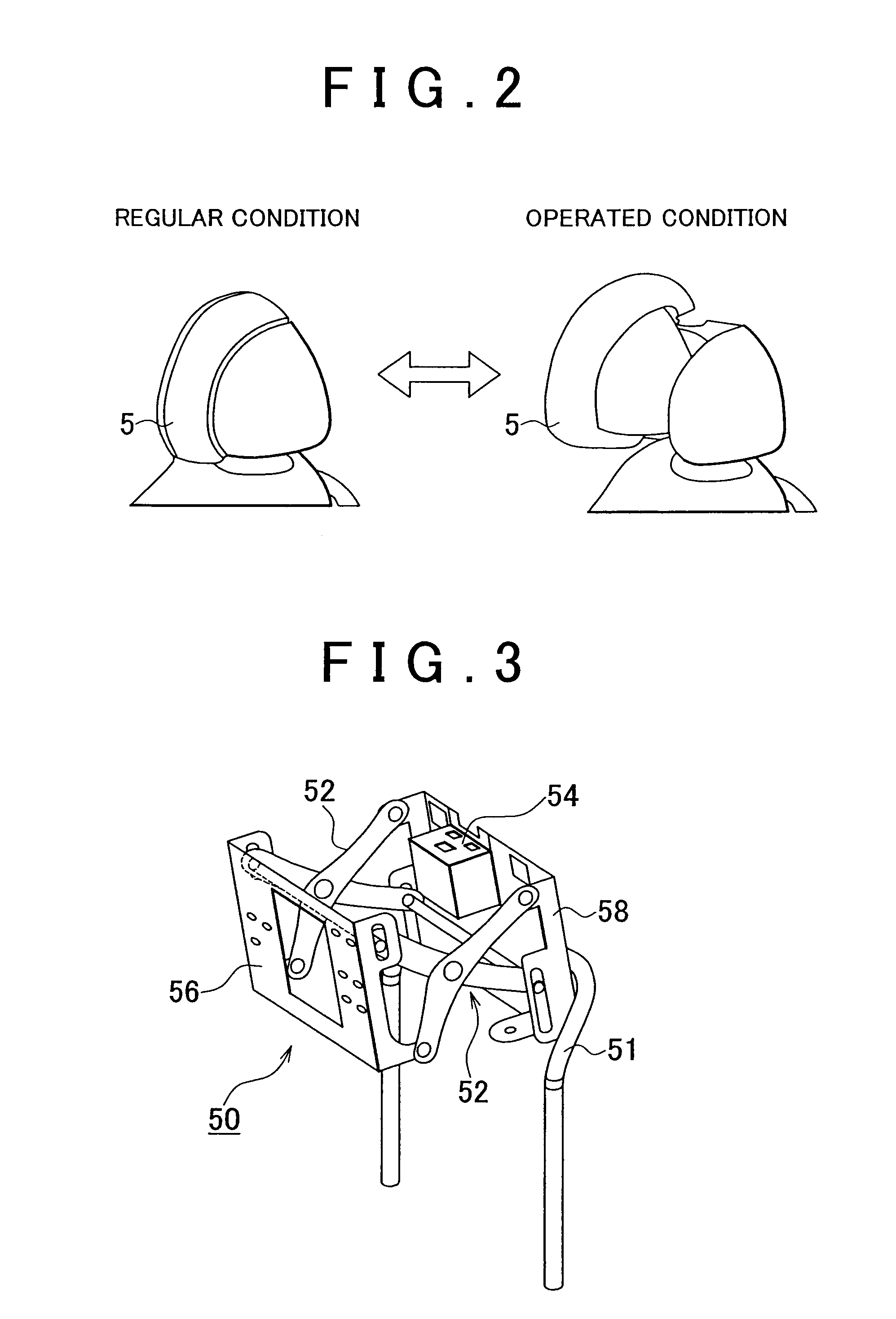
[0026]FIG. 1 is a system configuration view showing a headrest control apparatus according to an embodiment of the invention. In FIG. 1, main components of the headrest control apparatus are shown in a side view of a vehicle. FIG. 2 is a view showing a headrest 5 under the normal condition (in the retracted position) and the headrest 5 that has been moved toward the front of the vehicle (in the forward-moved position). FIG. 3 is a perspective view showing an example of a headrest forward / rearward moving mechanism 50 of an active headrest 70. FIG. 4 is a top view of the headrest 5, which shows the manner in which the headrest 5 is moved by a headrest rotating mechanism 60 of the active headrest 70. FIG. 5 is a perspective view showing an example of the headrest rotating mechanism 60 of the active headrest 70. FIG. 6 is a top view schematically showing the headrest rotating me...


PUM


Abstract

A headrest control apparatus includes: a headrest moving mechanism that supports a headrest in such a manner that at least one of a rotation of the headrest about an axis of the headrest, which extends in the vehicle-height direction, and a movement of the headrest in the vehicle-width direction is permitted; a drive unit that causes at least one of the rotation and the movement of the headrest; and a control unit that controls the drive unit.

Description

INCORPORATION BY REFERENCE[0001]The disclosure of Japanese Patent Application No. 2007-67166 filed on Mar. 15, 2007 including the specification, drawings and abstract is incorporated herein by reference in its entirety.BACKGROUND OF THE INVENTION[0002]1. Field of the Invention[0003]The invention relates to a headrest control apparatus, a headrest control method and an active headrest which move a headrest to prepare for a rear-end collision with a subsequent vehicle.[0004]2. Description of the Related Art[0005]A headrest apparatus for a vehicle, which includes a headrest that holds a passenger's head and that is fitted to a top end portion of a seat back, is described in, for example, Japanese Patent Application Publication No. 2003-191778 (JP-A-2003-191778). The headrest apparatus for a vehicle described in JP-A-2003-191778 further includes front holding means for moving a head holding portion of the headrest toward the front of a vehicle so that the passenger's head is held at a p...

Claims


Application Information

Patent Timeline
Patent Type & Authority Patents(United States)
IPC IPC(8): G06F17/00B60R22/00E05F15/00G05D1/00G06F7/00G05D3/00
CPCB60N2/002B60N2/0244B60N2/4228B60N2/4867B60N2/4885B60N2/4805B60N2002/0268B60N2/888B60N2/868B60N2/806B60N2/0268
Inventor UCHIDA, KIYOYUKITANAKA, YUICHI
Owner TOYOTA JIDOSHA KK
Why Eureka
Try Eureka