Retractable air deflection apparatus for reduction of vehicular air drag

a technology of air deflection apparatus and retractable air, which is applied in the direction of roofs, transportation and packaging, vehicle arrangements, etc., to achieve the effect of reducing both drag and associated drag

Inactive Publication Date: 2010-01-05
NUSBAUM HOWARD G
View PDF37 Cites 106 Cited by
  • Summary
  • Abstract
  • Description
  • Claims
  • Application Information

AI Technical Summary

Benefits of technology

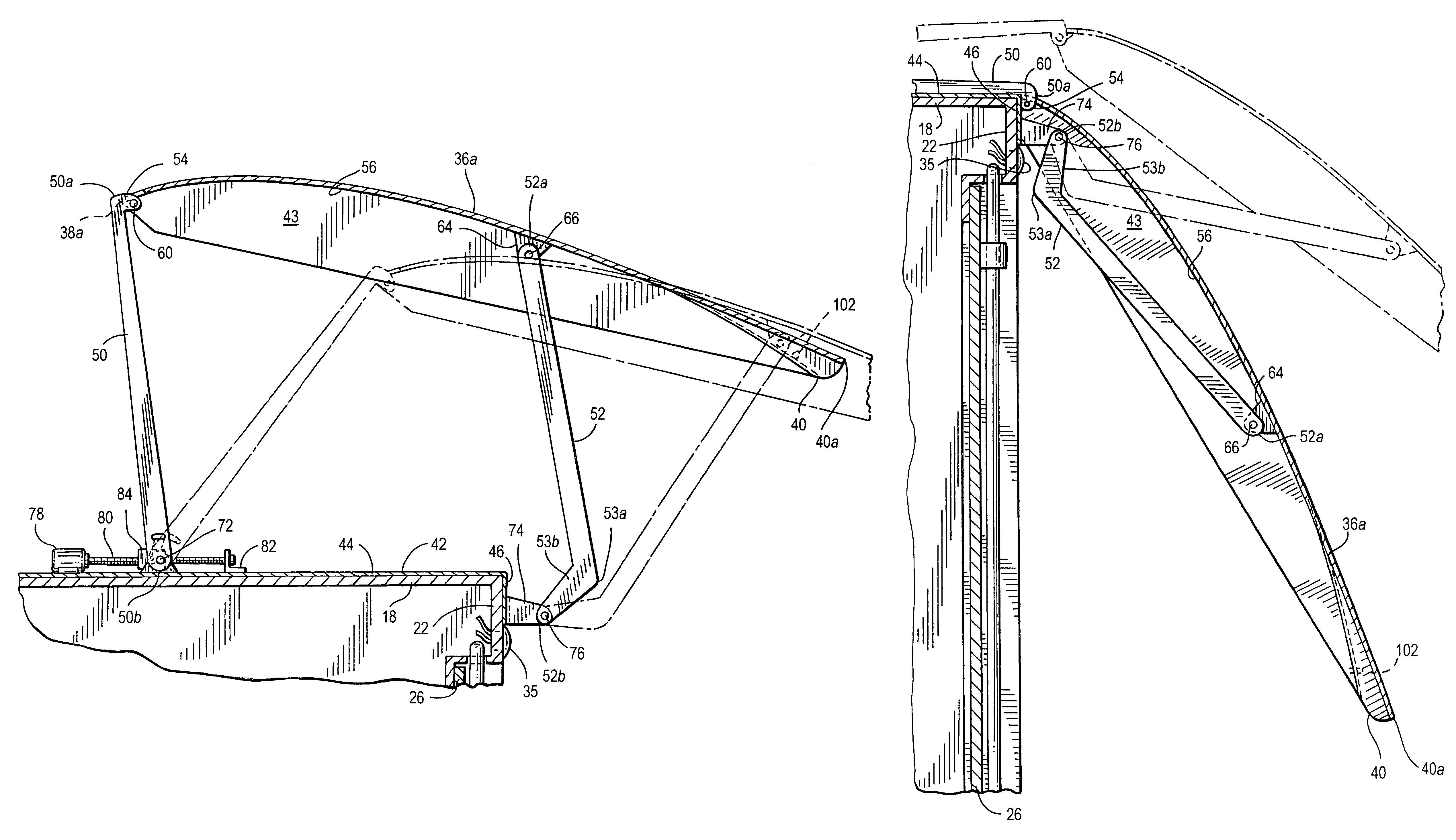
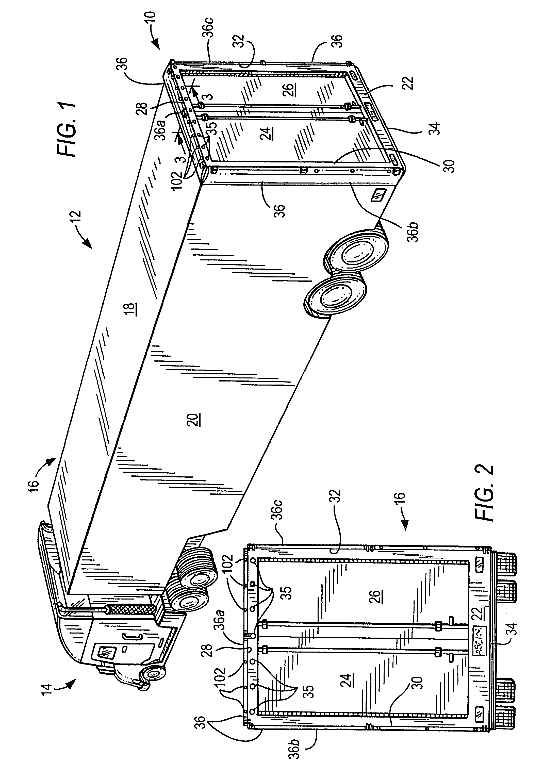
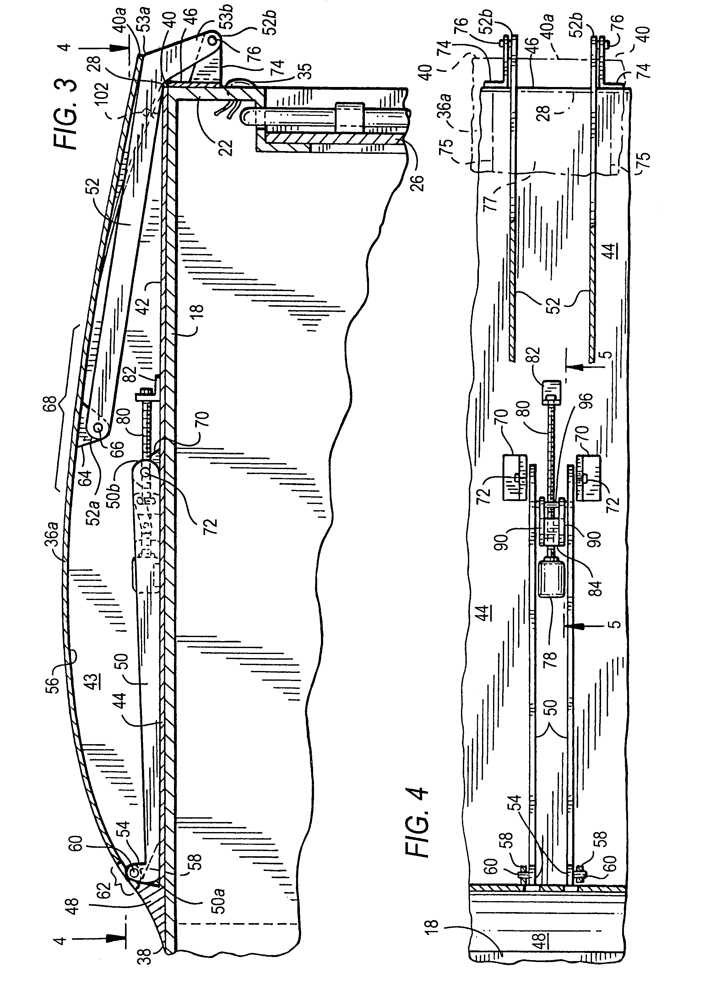
[0028]For vehicles in which the rear-facing surface comprises one or more doors allowing access to the interior of the vehicle for, e.g., loading or unloading of cargo, the air deflection elements are not coupled to these cargo doors, and therefore the deployment and retraction of the air deflection elements is independent of the position or movement of these cargo doors. As a result, the air deflection elements are capable of assuming a fully retracted position when these cargo doors need to be opened, but they do not automatically assume a deployed position once (i.e., they can remain in or assume the retracted position even when) the cargo doors of the vehicle are closed. Preferably, the air deflection elements are deployed only when the vehicle is in motion, and only to the extent necessary to optimize the aerodynamic drag reduction for the speed at which the vehicle is traveling, with the fully extended deployed position being utilized when the vehicle is moving at or close to its normally high operating speed. However, due to their aerodynamic shape, the air deflection elements can be effective, in certain embodiments, to counteract the breakdown in laminar flow along the top and sides of the vehicle, even when in their fully retracted position.
[0029]It is therefore one aspect of the present invention that when the vehicle is moving and the air deflection elements are deployed, both the drag associated with the area of low pressure which develops behind the vehicle, and the drag associated with the breakdown of the laminar air flow along the top and sides of the vehicle, are reduced as the air deflection elements divert the airflow from the trailing top and side surfaces of the vehicle.
[0030]It is another aspect of the present invention that when the vehicle is moving and the air deflection elements are not deployed, the air deflection elements may in certain configurations still provide some aerodynamic benefit, since the drag associated with the breakdown of the laminar air flow along the top and sides of the vehicle will be at least moderately reduced by the partial diversion of the airflow from the trailing top and side surfaces of the vehicle, thereby reducing turbulence by helping to at least partially re-establish laminar flow.
[0031]It is a feature of the present invention that the positions assumed by the air deflection elements can be changed dynamically, as the speed of the vehicle changes, in order to optimize their aerodynamic benefits in reducing drag.
[0032]It is another feature of the present invention that, depending upon the extent of deployment or the air deflection elements, the airflow along the top and sides of the vehicle can sometimes be diverted by being “ducted” or “scooped” by the inner surface of each air deflection element, and in other instances the airflow along the top and sides of the vehicle can be diverted by being “bent” over and around the outer surface of each air deflection element, while in still other instances the airflow can be diverted in both of these ways, thus utilizing both the inner and outer surfaces of each air deflection element simultaneously, so as to divert the airflow into the area behind the vehicle and thereby reduce in all cases the drag associated with the area of low pressure which develops behind the vehicle.
[0034]It is a further feature of the present invention that it can be used for aerodynamic benefit to reduce the airflow inefficiencies that result from the turbulence introduced by the gaps between the adjacent container bodies in vehicles having multiple successive box-shaped container units.

Problems solved by technology

Fuel consumption is a major operating cost for trucking and other forms of transportation.
As fuel costs have risen, the expense of fuel has become an increasingly important component in the operating expenses associated with transportation, and as such it has become a factor that affects the profitability of individual transportation companies and of the transportation industry generally.
Most trucks and other heavy land-based transport vehicles have boxy shapes which are inefficient aerodynamically, and therefore, when such a vehicle travels over a route at normal operating speeds, air flow resistance at the front of the vehicle, which tends to increase headwind or frontal pressure, and drag-producing air flow phenomena at the rear and along the sides of the vehicle, which tend to decrease trailing air pressure and to increase friction, combine to retard the forward movement of the vehicle and have always been major factors in wasted fuel economy.
Specifically, in order to maintain a chosen speed, additional engine power is required to overcome the air flow resistance and drag produced by these phenomena, which in turn leads to the consumption of more fuel.
As the speed of the vehicle increases, the effects produced by these phenomena can increase geometrically, such that at high operating speeds, most of the energy expended by the vehicle is consumed in overcoming these phenomena.
This frontal streamlining reduces the headwind, or front end pressure, but does nothing to address the similar but distinct problems caused by the air flow phenomena which produce drag, and which originate behind, or at or near the rear of such a vehicle, along its top and sides, to which the prior art has paid little attention.
The other factor that results in drag is due to an increase in friction arising from the disruption in laminar air flow longitudinally along the sides and along the top of a box-shaped vehicle as it progresses through the air along its forward path.
This disruption is characterized by eddies and turbulence that develop behind and along the top and sides of the vehicle as the laminar flow breaks down.
When traveling at slower speeds, the breakdown “boundary,” i.e., the point at which this effect is manifested, is located towards the rear of the vehicle, but as the speed increases, the breakdown boundary generally migrates forward, thus increasing the amount of friction experienced by the vehicle.
However, the first areas of such a vehicle that are affected by the breakdown in laminar flow are the top and sides, at or near the respective trailing edges.
However, the hinged panels of Roberge et al. are flat or planar, rather than curved, and they are attached to the hinged pair of rear cargo doors which form a portion of the rear-facing surface of the vehicle; thus, they are caused to retract only when those cargo doors are opened, and they cannot be used with vehicles that employ a single, “roll-up” rear cargo door (rather than a pair of swinging cargo doors), since no means to access such a unitary door (or the cargo inside) is provided.
Moreover, these panels, which primarily provide for an improved laminar flow by altering the shape, i.e., by streamlining, the rear side and upper rear edges of the trailer, do not directly address the problem of reduced trailing pressure, and therefore do not divert the air sufficiently to alleviate the area of low pressure behind the vehicle (although a modest diversion or deflection of the airstream does occur as the air is “bent” slightly around the panels).
As a result, the solution proposed by Roberge et al. functions best only at higher operating speeds, since it does not provide for “scooping” or “ducting” of the air, which is desirable at lower operating speeds in order to reduce the trailing low pressure behind the vehicle as well as to improve the laminar flow along the top and sides of the vehicle.
On the other hand, while U.S. Pat. No. 5,280,990 to Rinard does provide curved, vertically-oriented side deflection vanes (as well as horizontally-oriented transverse upper and lower deflection ducts, which act to “scoop” or divert at right angles the air flow above, below and along the sides of the vehicle, and which are therefore primarily directed towards reducing the area of low pressure behind the vehicle), Rinard's air diversion elements do not directly address the additional drag caused by the breakdown in laminar flow along the top and sides of the vehicle (although a slight improvement in the laminar flow does occur simply by virtue of the reduction in the trailing low pressure that these elements do provide).
Nevertheless, and in contrast to Roberge et al., the solution proposed by Rinard works well to reduce drag only at lower operating speeds, but does not work well at higher operating speeds, when there is more of a need for the airstream to be diverted from the trailing top and side surfaces by flowing over the air diversion elements, rather than being “ducted” under and / or through them.
In fact, at higher speeds Rinard's solution not only becomes less effective, it actually becomes counter-effective as the vehicle speed increases, because as the airflow that is “ducted” through these elements increases, they eventually become aerodynamically resistive.
In addition, Rinard's side deflector vanes, like the planar panels of Roberge et al., are attached to the hinged pair of rear cargo doors which form a portion of the rear-facing surface of the vehicle, and although they can be displaced from their deployed position, this can be done only when the cargo doors of the trailer are opened, and even then, Rinard's side deflector vanes cannot be retracted to a fully flush position.
Thus, while these deflector vanes need not be directly deployed and retracted manually in order to provide access to the cargo doors, they nevertheless remain deployed unless and until the cargo doors are actually opened, and accordingly, they are susceptible to damage when the vehicle is being maneuvered into a narrow loading dock, and / or they can interfere with the driver's ability to monitor road conditions behind the vehicle, especially when it is being operated on local streets or otherwise at slow (i.e., non-highway) speeds, or when it is being backed into a loading dock, or when it is being parked.
Furthermore, during high speed travel the instabilities resulting from the breakdown in the laminar airflow along the top and sides of the vehicle are likely to cause rapid oscillation of Rinard's side deflector vanes (despite their spring-biased mounting means), possibly resulting in those deflector vanes being damaged or, more likely, being forced by the unstable airflow into a “closed” position flush with the trailing edges of the vehicle body (completely overcoming the bias of the springs), and thereby making the vanes utterly ineffective to perform their intended air diversion or “scooping” function.
Thus, although the prior art appears to have recognized that the trailing upper (and, to a smaller degree, lower) edge of a box-shaped vehicle would create low pressure behind the rear of the vehicle when it is in motion, the prior art has failed to address that low pressure problem while also addressing the problems that arise from the simultaneous disruption of laminar flow along the top and sides of a vehicle.
The prior art has also failed to recognize that the magnitude of each of these problems, both absolutely and relative to one other, and the nature of their most effective solutions, will vary according to the speed of the vehicle, and the prior art has failed address these problems in a manner that can not only dynamically adjust, but can also optimize, those solutions as the speed changes.
While the drag problems resulting from the trailing low pressure and disruption of laminar flow described above are particularly acute for cargo-carrying vehicles which travel over highways and other paved or unpaved roads, such as conventional tractor-trailers and other box-shaped trucks, and even squared-off passenger-carrying vehicles such as buses and sport-utility vehicles, they can also afflict other large land-based conveyances, particularly combination or “tandem” tractor-trailer assemblies comprising two or even three box-shaped trailers, and even a succession of adjacent, squared-off railroad cars (regardless of whether those rail cars are used for carrying passengers or freight).
In the latter cases, in which there are multiple box-shaped container units, additional airflow inefficiencies are created, due to the breakdown in laminar flow in between the units caused by the gaps between the adjacent container bodies, which the prior art has also failed to address.
Moreover, Rinard's deflectors might actually have an undesirable, negative effect in this “tandem” context, since they will actually foster a breakdown in laminar flow at lower speeds than would otherwise be the case if those deflectors were not present, thus actually reducing, rather than improving, aerodynamic efficiency at any given speed.
Another related factor which can affect vehicle performance, and therefore fuel consumption, is the airflow both over and under the vehicle, as it moves along its route at high speeds.
The prior art, as exemplified by the Rinard and Roberge et al. patents mentioned above, has failed to address the lift problem attributable to the Bernoulli effect in the same context as the problems created by the air flow phenomena which produce drag.
In summary, the prior art has failed to provide a solution that satisfactorily ameliorates all of the components of trailing drag which develop at or near the rear of a box-shaped vehicle, both behind it and along its top and sides, as it moves forward at normal operating speeds.
Moreover, and particularly for road vehicles, the prior art has failed to provide such a solution which at the same time does not hinder or obstruct the driver's view of the area surrounding the rear of such a vehicle when it is being operated at slower and maneuvering speeds, and does not interfere with access to, or with the opening and closing of, the rear cargo door(s) which could unduly prolong loading and / or unloading operations at a conventional loading dock.
Furthermore, and again particularly for road vehicles such as tractor-trailers and other box-shaped trucks, the prior art has failed to provide such a solution which also helps to overcome the lifting force encountered at highway speeds.
Finally, the prior art has failed to appreciate that any measures used to counteract the aerodynamic inefficiencies that plague box-shaped vehicles must account for the fact that these aerodynamic instabilities, as well as the effectiveness of the countermeasures, will vary as the speed of the vehicle changes.

Method used


Image

  • Retractable air deflection apparatus for reduction of vehicular air drag
  • Retractable air deflection apparatus for reduction of vehicular air drag
  • Retractable air deflection apparatus for reduction of vehicular air drag

Examples


second embodiment

[0180]Referring next to FIGS. 29-31 in addition to the aforementioned FIGS. 1-28, the alternative, but still preferred, embodiment of the retractable air deflection apparatus of the present invention, mentioned in passing hereinbefore, will now be described in further detail. In this second embodiment, the shapes of the air deflection elements 336 themselves do not differ significantly from the shapes of the air deflection elements 36 of the most preferred embodiment, such that the shapes of the air deflection elements 336 as shown in the drawings may be symbolized by the same modified four-digit NACA numbers, 9401-01 and / or 9401-11, as were used to represent the shapes of the air deflection elements 36, as illustrated in FIGS. 3-11A (and such that the same ten modified four-digit NACA numbers as are set forth above symbolize other exemplary airfoil shapes that will be acceptable for use with the this second embodiment of the present invention). However, there are significant differ...

third embodiment

[0209]Referring next to FIGS. 47-50 in addition to the aforementioned FIGS. 1-46, another alternative, but also still preferred, embodiment of the retractable air deflection apparatus of the present invention will now be described, illustratively in conjunction with a long-haul vehicular environment exemplified by the same tractor-trailer 12 as shown in FIGS. 1-22. In this third embodiment, there are significant differences in the air deflection elements themselves, and in the structures that support and link each air deflection element to the vehicle body, as well as in the manner in which each air deflection element is deployed and retracted, as compared with the embodiments described previously. However, this embodiment preferably does include drive components to assist with the deployment and retraction of the air deflection elements.

[0210]In this embodiment, the air deflection apparatus 510 comprises at least one, and preferably at least three, air deflection elements 536 (one ...

fourth embodiment

[0251]As will be evident, the alternate structure for a lower air deflection element as just described may be used for the upper, left side and right side air deflection elements as well, and referring now to FIGS. 67-69 in addition to the aforementioned FIGS. 1-66, such an arrangement constitutes the retractable air defection apparatus of the present invention, which is generally designated by the reference numeral 711, and which will now be described, illustratively in conjunction with a medium-haul vehicular environment exemplified by a vehicle 714′ which is similar to the vehicle 714 as shown in FIGS. 60-69, but which has a roll-up door 724′ of smaller dimension, and consequently has a rear-facing surface 722′ that encompasses greater surface area, in that it is wider on either side of that door than is shown for vehicle 714 in FIG. 60 (or for vehicle 312 in FIG. 27), and in that it extends downward further from the upper trailing corner edge of the cargo compartment than is sho...


PUM


Abstract

An air deflection apparatus for reduction of vehicular air drag comprises at least one air deflection element coupled to a rear portion of the vehicle but not to the rear-facing surface of the vehicle or, in other embodiments, at least one air deflection element coupled to a rear portion of the vehicle but not to any rear door which the vehicle may have. The air deflection elements are displaceable, preferably in unison, between a retracted position and at least one deployed position in which the air deflection elements intersect with the air flowing around the top and sides, and preferably also the bottom, of the vehicle, and in which they divert that airflow in a manner that enhances the aerodynamic characteristics of the vehicle and thereby improves its fuel economy, resulting in a reduction in fuel cost. The air deflection elements may be deployed and retracted manually, or remotely with powered assistance, or under microprocessor control, with the latter allowing for optimal positioning of the air deflection elements based either on pre-stored values, or on values derived, utilizing an optional feedback mechanism, from real-time vehicular speed and fuel consumption data. Vehicles equipped with the apparatus, and methods of reducing vehicular air drag using the apparatus, are also disclosed.

Description

REFERENCE TO RELATED APPLICATIONS[0001]This application claims the benefit of prior co-pending U.S. Provisional Patent Application Ser. No. 60 / 852,736, filed Oct. 19, 2006.TECHNICAL FIELD[0002]This invention relates to an improvement in the aerodynamic characteristics of vehicles. More specifically, this invention relates to an air deflection apparatus for box-shaped land transportation vehicles, such as trucks and the like, which provides a reduction in the aerodynamic drag that normally results from the movement of such vehicles through the air at various speeds. Even more specifically, this invention relates to at least one retractable air deflection element, which may be disposed adjacent the angular trailing corner edge(s) of a box-shaped vehicle body, and which, in the preferred embodiment, can assume at least three positions: a closed or retracted position, which provides a modicum of aerodynamic drag reduction, a deployed position providing additional aerodynamic drag reduct...

Claims


Application Information

Patent Timeline
Patent Type & Authority Patents(United States)
IPC IPC(8): B62D35/00
CPCB62D35/001
Inventor NUSBAUM, HOWARD G.
Owner NUSBAUM HOWARD G
Why Eureka
Try Eureka