Methods and systems for gas turbine engine control

a technology for gas turbine engines and control systems, applied in the field of gas turbines, can solve the problems of poor tracking action of the control system with the controlled parameter, and achieve the effects of reducing the response time of the gas turbine fuel control system to changes in fuel pressure, reducing the response time and increasing the bandwidth of the response of the fuel control valv

Active Publication Date: 2010-01-12
GENERAL ELECTRIC CO
View PDF14 Cites 38 Cited by
  • Summary
  • Abstract
  • Description
  • Claims
  • Application Information

AI Technical Summary

Benefits of technology

[0004]In one embodiment, a control system includes a component model adapted to regulate a fuel supply pressure for a gas turbine, a pressure sensor adapted to sense a pressure of fuel supplied to the gas turbine, and a feedback module including integral plus state feedback, the feedback module adapted to provide a positive feedback reference signal to the component model such that a response time of the gas turbine fuel control system to changes in fuel pressure is facilitated being reduced.
[0005]In another embodiment, a method for controlling a dynamic response of a fuel control valve in a gas turbine fuel control system includes regulating a fuel supply pressure for a gas turbine using a component model, sensing a pressure of a fuel supply to the gas turbine, and applying integral plus state feedback to the component model to facilitate at least one of reducing a response time of the fuel control valve to changes in the fuel supply pressure and increasing the bandwidth of the fuel control valve response.
[0006]In yet another embodiment, a gas turbine engine assembly includes a combustor adapted to receive a flow of fuel from a fuel supply system through a fuel supply control valve, and a control system adapted to facilitate controlling a dynamic response of the fuel supply control valve wherein the control system includes a processor adapted to regulate a fuel supply pressure to the combustor using a component model, receive a pressure signal of the fuel supply to the combustor, and apply integral plus state feedback to the component model to facilitate reducing a fuel control valve response time to a change in fuel supply pressure to the combustor.

Problems solved by technology

A slow response and low bandwidth may result in a poor tracking action of the control system with the controlled parameter.

Method used


Image

  • Methods and systems for gas turbine engine control
  • Methods and systems for gas turbine engine control
  • Methods and systems for gas turbine engine control

Examples


Embodiment Construction

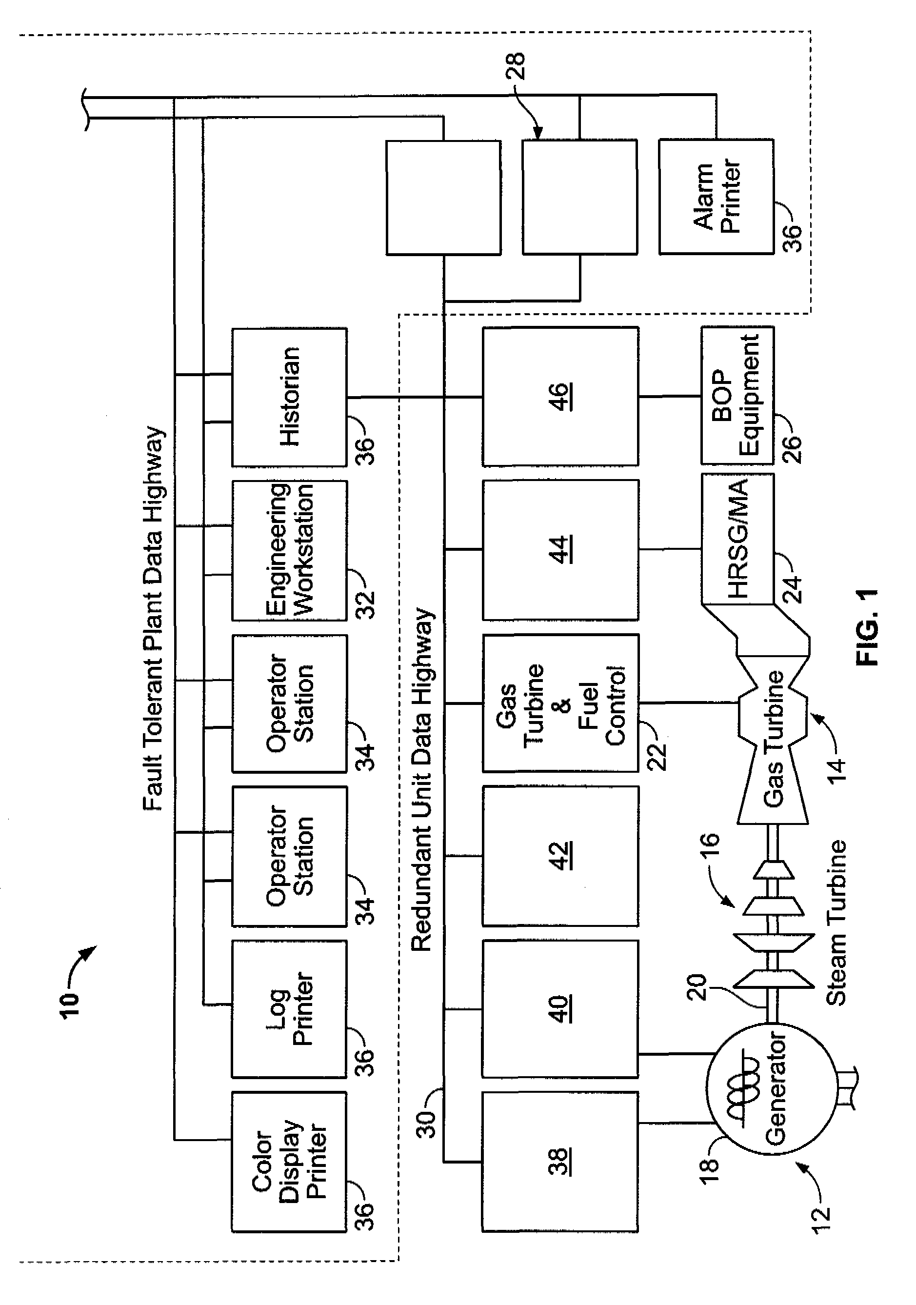
[0010]FIG. 1 is a schematic view of an exemplary control system 10 for a power generation plant 12 including a gas turbine engine 14. In the exemplary embodiment, gas turbine engine 14 is coupled to a steam turbine 16 and an electric power generator 18 through a monolithic shaft 20 in a combined cycle configuration. In various other embodiments of the present invention, gas turbine engine 14 is coupled to a generator in a simple cycle gas turbine engine configuration. additional configurations of a gas turbine engine with other prime movers are also contemplated with regard to the various embodiments of the present invention.

[0011]In the exemplary embodiment, gas turbine engine 14 is controlled by control system 10 through a gas turbine and fuel control subsystem 22. Other equipment such as steam turbine 16, a heat recovery steam generator 24, and balance of plant equipment 26 are controlled by control system 10 through respective control subsystems in power generation plant 12. The...


PUM


Abstract

Methods and systems for controlling a dynamic response in a gas turbine fuel control system are provided. The control system includes a component model adapted to regulate a fuel supply pressure for a gas turbine, a pressure sensor adapted to sense a pressure of fuel supplied to the gas turbine, and a feedback module including integral plus state feedback, the feedback module adapted to provide a positive feedback reference signal to the component model such that a response time of the gas turbine fuel control system to changes in fuel pressure is facilitated being reduced.

Description

BACKGROUND OF THE INVENTION[0001]This invention relates generally to gas turbines and more particularly to fuel control systems for gas turbines.[0002]At least some known industrial gas turbine fuel control systems rely upon steady fuel pressure upstream of a set of parallel gas control valves for proper operation. For this reason, a pressure control valve is employed immediately upstream of the set of parallel gas control valves, to regulate this pressure.[0003]Improvement to the pressure control valve response is desirable for gas turbine fuel system pressure control. A slow response and low bandwidth may result in a poor tracking action of the control system with the controlled parameter. An algorithm that provides an improved fuel control system dynamic response, including a shorter rise time of the response and better tracking action for higher frequency command reference signals tends to improve overall turbine system operation.BRIEF DESCRIPTION OF THE INVENTION[0004]In one em...

Claims


Application Information

Patent Timeline
Patent Type & Authority Patents(United States)
IPC IPC(8): F02C9/00
CPCF02C9/28F05D2270/301F02C9/00F02C9/26
Inventor FEIZ, MAJID
Owner GENERAL ELECTRIC CO
Why Eureka
Try Eureka